Posts Tagged ‘Watt’

Calculating Kinetic Energy By Means of the Work of Friction

Wednesday, May 25th, 2016

    My activities as an engineering expert often involve creative problem solving of the sort we did in last week’s blog when we explored the interplay between work and kinetic energy.   We used the Work-Energy Theorem to mathematically relate the kinetic energy in a piece of ceramic to the work performed by the friction that’s produced when it skids across a concrete floor.   A new formula was derived which enables us to calculate the kinetic energy contained within the piece at the start of its slide by means of the work of friction.   We’ll crunch numbers today to determine that quantity.

    The formula we derived last time and that we’ll be working with today is,


Calculating Kinetic Energy By Means of the Work of Friction

Calculating Kinetic Energy By Means of the Work of Friction


where, KE is the ceramic piece’s kinetic energy, FF is the frictional force opposing its movement across the floor, and d is the distance it travels before friction between it and the less than glass-smooth floor brings it to a stop.

    The numbers we’ll need to work the equation have been derived in previous blogs.   We calculated the frictional force, FF, acting against a ceramic piece weighing 0.09 kilograms to be 0.35 kilogram-meters/second2 and the measured distance, d, it travels across the floor to be equal to 2 meters.   Plugging in these values, we derive the following working equation,

KE = 0.35 kilogram-meters/second2 × 2 meters

KE = 0.70 kilogram-meters2/second2

    The kinetic energy contained within that broken bit of ceramic is just about what it takes to light a 1 watt flashlight bulb for almost one second!

    Now that we’ve determined this quantity, other energy quantities can also be calculated, like the velocity of the ceramic piece when it began its slide.   We’ll do that next time.

Copyright 2016 – Philip J. O’Keefe, PE

Engineering Expert Witness Blog

____________________________________


Transistors – Voltage Regulation Part X

Monday, September 24th, 2012
     Through the ages it’s been common practice to name important discoveries after those who discovered them.  For example, James Watt was a mechanical engineer who improved the steam engine by finding a solution to the problem of steam condensing into water inside the engine, a phenomenon which resulted in the engine cooling and reducing its efficiency.  Thus it was fitting that a metric unit of power, the watt, was named in his honor.  Today we’ll become acquainted with the man behind the naming of the Zener diode, Clarence Zener, and take a look at his contributions with regard to the function of this electrical component.

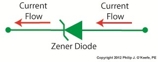
     Last time we began our discussion on electrical components known as diodes and saw how they’re used on circuit paths to govern the flow of current.  The Zener diode is a particular type of diode and a key component in transistorized voltage regulator circuits, as we’ll see later.  For now, let’s see how it works.     The symbol for the Zener diode is almost identical to that of a standard diode, introduced in my previous blog, but the Zener version has a bent line going through it resembling a distorted letter “z.”  See Figure 1.

Zener diode voltage regulator

Figure 1       


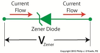
      Electric current flows through the Zener Diode just as it does through a standard diode.  But when the current flows in reverse, that’s where the similarity ends.  See Figure 2.

  Zener diode

Figure 2    


     When current tries to flow in the reverse direction, the Zener diode acts as an electrical conductor and allows current to pass through it.  In other words, it doesn’t block current flow as standard diodes do.

      At this point, you may be asking, “What’s so special about that?”  Perhaps you’ve made the connection that it behaves no differently than a metal wire.  But that isn’t entirely correct.

     You see, when current passes in the reverse direction through the Zener diode, it maintains a constant voltage.  This is called the Zener Voltage and is denoted as VZener.  The significance here is that within the circuit, any electronic component connected across the leads of a Zener diode will be supplied with a constant, unchanging voltage.  Thus the Zener diode works as a voltage regulator, enabling devices connected to it to have smooth, uninterrupted operation at a constant voltage.  It should be noted that this phenomenon only happens when the current flowing through the Zener diode is flowing in reverse.

     Next time we’ll look at a basic regulated power supply circuit to see how a Zener diode is incorporated in order to maintain a consistent output voltage.

____________________________________________

Wire Size and Electric Current – Joule Heating

Sunday, March 20th, 2011
     Ever take a peek inside the toaster while you’re waiting for the toast to pop up?  If so, you would have noticed a bright orange glow.  That glow is produced when the toasting wires heat up, which in turn creates a nice crusty surface on your bread or waffle.  It’s the same phenomenon as when the filament inside an incandescent bulb glows.  The light and heat produced in both these cases are the result of the Joule, pronounced “jewel,” effect at work.

     To understand Joule heating, let’s first refresh our memories as to electrical current resistance.  We learned previously that wire is not a perfect conductor, and as such resistance to flow is encountered.  This resistance causes power to be lost along the length of wire, in accordance with this equation:

Power Loss = I2 × R

Where I is the electric current flowing through a wire, and R is the total electrical resistance of the wire.  The power loss is measured in units of Joules per second, otherwise known as watts, “watt” denoting a metric unit of power.  It is named after the famed Scottish mechanical engineer, James Watt, who is responsible for inventing the modern steam engine.  A Joule is a metric unit of heat energy, named after the English scientist James Prescott Joule.  He was a pioneer in the field of thermodynamics, a branch of physics concerned with the relationships between different forms of energy.

     Anyway, to see how the equation works, let’s look at an example.  Suppose we have 12 feet of 12 AWG copper wire.  We are using it to feed power to an appliance that draws 10 amperes of electric current.  Going to our handy engineering reference book, we find that the 12 AWG wire has an electrical resistance of 0.001588 ohms per foot, “ohm” being a unit of electrical resistance.  Plugging in the numbers, our equation for total electrical resistance becomes:

R = (0.001588 ohms per foot) × 12 feet = 0.01905 ohms

And we can now calculate power loss as follows:

Power = I2 × R = (10 amperes)2 × (0.01905 ohms) = 1.905 watts

     Instead of using a 12 AWG wire, let’s use a smaller diameter wire, say, 26 AWG.  Our engineering reference book says that 26 AWG wire has an electrical resistance of 0.0418 ohms per foot.  So let’s see how this changes the power loss:

R = (0.0418 ohms per foot) × 12 feet = 0.5016 ohms

Power = I2 × R = (10 amperes)2 × (0.5016 ohms) = 50.16 watts

     This explains why appliances like space heaters and window unit air conditioners have short, thick power cords.  They draw a lot of current when they operate, and a short power cord, precisely because it is short, poses less electrical resistance than a long cord.  A thicker cord also helps reduce resistance to power flow.  The result is a large amount of current flowing through a superhighway of wire, the wide berth reducing both the amount of power loss and the probability of dangerous Joule heating effect from taking place. 

     Our example shows that the electric current flowing through the 12 AWG wire loses 1.905 watts of power due to the inconsistencies within the wire, and this in turn causes the wire to heat up.  This is Joule heating at work.  Joule heating of 50.16 watts in the thinner 26 AWG wire can lead to serious trouble.

     When using a power cord, heat moves from the copper wire within it, whose job it is to conduct electricity, and beyond, on to the electrical insulation that surrounds it.  There the heat is not trapped, but escapes into the environment surrounding the cord.  If the wire has low internal resistance and the amount of current flowing through it is within limits which are deemed to be acceptable, then Joule heating can be safely dissipated and the wire remains cool.  But if the current goes beyond the safe limit, as specified in the American Wire Gauge (AWG) table for that type of wire, then overheating can be the result.  The electrical insulation may start to melt and burn, and the local fire department may then become involved.

         That’s it for wire sizing and electric current.  Next time we’ll slip back into the mechanical world and explore a new topic: the principles of ventilation.

_____________________________________________