| Ever venture into your basement and stare in amazement at the labyrinth of ductwork stemming off from the furnace? Believe it or not, there’s a science behind that spaghetti bowl configuration. Ductwork can either be flexible or rigid, square or round in shape. Its job in a local exhaust ventilation system is to carry airborne contaminants from the originating source, the carefully positioned hood in the workplace, to the exhaust stack where it is vented outside the building. This job isn’t an easy one. Fluids, like air thick with toxins and toxic gases, don’t want to flow very well through ductwork unless you make their path as unimpeded as possible.
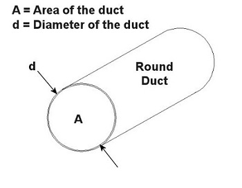
You can think of the air and contaminants flowing through ductwork as if it were like a car moving down a highway. Expressways don’t have sharp 90 degree turns or abrupt changes in width. These would cause a slow down in traffic, unless of course an accident is in the way. Expressways also tend to be rather large thoroughfares. The science behind ductwork follows the same basic principles to work effectively. It will minimize or eliminate sharp turns and it will avoid any abrupt changes in diameter. It will also be as wide in diameter as the environment will accommodate in order to move air volume most effectively. A local exhaust ventilation system’s performance can be greatly hampered and workers exposed to hazards if ductwork leaks. And if the leaks are upstream of the fan and large enough, they can reduce the ability of the local exhaust ventilation system to draw the airborne contaminants into the hood. Air starts getting drawn in through the leaks rather than through the hood. If the leaks are downstream of the fan, the airborne contaminants can re-enter the work area through the leaks rather than going outside through the exhaust stack. Ducts come in an endless variety of diameters, the diameter being part of a simple mathematical equation relating to flow velocity. In the simplest of terms, the flow of air through ductwork is governed by the following equation: Q = V × A where Q is the flow rate of air through the duct in cubic feet per minute (CFM), V is velocity of the air flow in feet per minute, and A is the cross sectional area of the duct in square feet. As an example, suppose you want to design a local exhaust ventilation system with ducts no greater than 5 inches in diameter because of space and clearance limitations. You want to use round ducts for the system because they handle air more efficiently and have no sharp corners where dust can collect. If an industrial hygienist determines that the air is required to flow at a minimum of 800 feet per minute through the duct, what is the airflow rate through the duct? Well, since we are dealing with a round duct, its cross sectional area is that of a circle: A = (π × d2) ÷ 4 where d is the diameter of the inside of the duct as shown in Figure 1 below. Figure 1 – Cross Section of a Round Duct So to use this equation for area, to solve for Q, then we must first convert the duct diameter from inches to feet, which makes our equation look like this: 5 inches ÷ 12 inches per foot = 0.416 feet This gives us a duct cross sectional area of: A = (π × (0.416 feet) 2) ÷ 4 = 0.136 square feet And the air will flow through the duct at this rate: Q = V × A = 800 ft./minute × 0.136 ft.2 = 108.8 CFM This air flow rate is good to know, because it will help the designer to select an appropriate fan for the local exhaust ventilation system. This is because fans are listed in manufacturers’ catalogs according to how many CFM they can handle. Next time, we’ll learn more about the rest of the local exhaust ventilation system, namely, the filter, fan, and exhaust stack. _____________________________________________ |
Archive for April, 2011
Industrial Ventilation – Local Exhaust Ventilation Ductwork
Monday, April 25th, 2011Industrial Ventilation – Local Exhaust Ventilation Hoods
Sunday, April 17th, 2011| I’m a husband who occasionally does a little vacuuming, at least of the areas I’m responsible for messing up. It’s not one of my favorite activities, and I particularly hate it when I’m in a hurry and I don’t have enough time to move things out of the way. That’s when an accident is prone to happen, and I end up sucking something besides dirt into the hose. The extra work I’ve just created for myself results in my having to open up the vacuum bag and start sifting through the debris. In the end, I sometimes end up making a bigger mess than the one I started out with.
Vacuums are wonderful tools, when used correctly. And when you think about it, the constituent elements of a household canister vacuum cleaner are similar to those of an industrial local exhaust ventilation system. My home vac is comprised of five main elements, all of which most of you are familiar with: a nozzle, hose, filter, a fan located inside the canister to provide suction, and an exhaust hole, also located within the canister, which serves to discharge newly filtered air back into the atmosphere. Industrial usage local exhaust ventilation systems also typically consist of five constituent elements, namely, a hood, ducts, an air cleaning device, a fan, and an exhaust stack. Like my home vacuum its main objective is to suck something in, namely, contaminated air. Let’s take a closer look at each of the parts. The hood is located at the beginning of the local exhaust ventilation system, and like your home vac’s nozzle, it’s positioned in close proximity to the area requiring cleaning. The objective is of course to capture contaminants at the source. Now placement of the hood within the work area is very important. Ultimately it must be far enough away from the source of contamination so as not to interfere with the work that’s being done, yet close enough to prevent contaminants from escaping. Hoods that almost completely enclose the work area provide the best control of contaminants. Trouble is, they can interfere with the work process. That’s where a specific design of hood, known as a “capture exhaust hood” comes in handy. This type of hood is attached to a flexible duct that resembles a super-sized vacuum cleaner hose. This arrangement provides greater flexibility than a huge, all-encompassing hood, and it also allows the hood to be easily positioned anywhere within the workplace as necessary. Again, placement of a capture exhaust hood is critical to its effective operation. Say for instance that a hood is initially positioned a mere two inches from a source of fumes, then someone comes along and bumps it. It ends up being four inches away from the source, and now it will require around three times the amount of air volume through the system to provide the same degree of capture as it did when it was just two inches away. If the ventilation system isn’t strong enough to draw in this extra volume of air, fumes will escape into the work area, rendering our cleanup efforts ineffective. Next time we’ll discuss the second main component in a local exhaust ventilation system, its ductwork. _____________________________________________ |
Industrial Ventilation – Local Exhaust Ventilation
Sunday, April 10th, 2011| My wife often says I’m the worst cook she knows. This doesn’t really bother me too much, because she’s the best cook I know, and she keeps me well fed. But there are times that I have to fend for myself in the kitchen, and this sometimes results in a foul smelling mess plastered all over the stove. Lucky for me we have a nice exhaust hood, and it usually manages to suck out the odor before my wife gets home.
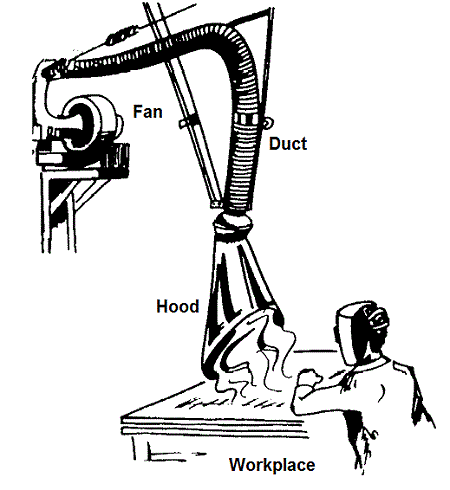
Local exhaust ventilation systems, like the vent over my stove, work much the same way in an industrial setting, albeit on a larger scale. This type of ventilation system gets its name because its action is quite specific, localized to contain exhaust air from a particular area. They’re routinely placed as close as possible to the source of contaminants, and they are able to work quickly to capture and expel chemical vapors, dusts, and fumes, before they spread. This type of ventilation is effective for other reasons, too, because it helps keep down heating and cooling costs. Instead of treating an entire building for ventilation issues, the problem can be nipped in the bud at its source. In many situations, local exhaust ventilation is preferred over dilution ventilation systems for these very reasons. A basic local exhaust ventilation system is comprised of a duct, a fan, and a hood as shown in Figure 1 below. One end of the duct is attached to the intake of the fan. The other end of the duct is attached to the hood. The duct can be rigid or flexible. The hood is positioned in the workplace near the source of contaminants. Figure 1 – Basic Local Exhaust Ventilation System This local exhaust ventilation system operates by much the same principle as the one generally governing the movement of liquids and gases. If you’re a regular reader of this blog, you’ll remember me writing that liquids and gases always flow from areas of higher pressure to those of lower pressure. Well, the air within the room has pressure principles at play as well, and the air within a given work area is at atmospheric pressure. When the fan is introduced into the scenario, a vortex is created within the duct which is less than that of the atmospheric pressure in the room. This difference in pressures causes the room air to flow into the ventilation duct along with its contaminants. The room air and contaminants flow out through the ventilation system, where they are then exhausted outside of the building. But because room air is being drawn into the ventilation system, provisions must be made to supply enough replacement air. Without the proper ratio of air moving in to that moving out, a ventilation system will not work properly. In other words, the suction created by the local ventilation system could cause the pressure in the room to drop below atmospheric pressure. This could cause the higher atmospheric pressure outside the room to bear down on doors, making them difficult to open. Worse yet, contaminants could back up into the room, causing workers to get sick. Now that we’ve covered the basics of local exhaust ventilation, we can move on to its five constituent elements and a discussion of their design. We’ll do that next week. _____________________________________________ |
Industrial Ventilation – Dilution Ventilation
Sunday, April 3rd, 2011| If you’re a fan of the new hit HBO series, Boardwalk Empire, then you know a lot about the effects of Prohibition. But did you know that Prohibition is responsible for the creation of mixed drinks? Until then, people drank their liquor straight. Then along came Prohibition, mob rule, and the desire to keep the booze, including some with questionable origins, flowing. This booze didn’t taste so good, and the addition of a sugary beverage to it, that is, diluting it with soda or juice, made it a lot easier to go down. By the time Prohibition was repealed in 1933, the mixed drink had taken a firm foothold in American society.
Most adults are aware of the fact that liquor, in excess, is toxic to the body. Too much of it, and the liver, which acts as a filtration device, itself becomes toxic. When that happens, poor health will follow. The same principle applies to air within a building. If it becomes thick with toxic fumes or potentially flammable vapors, indoor air quality will suffer. But if you infuse fresh air into the environment, the toxic load is diluted, making the environment habitable and safe. This addition of fresh air is called, appropriately enough, dilution ventilation. Now, the easiest way to create a dilution ventilation system is to open a window. Trouble is there often isn’t enough natural airflow to do much good. But if you step up the effort by introducing a mechanical ventilation system, complete with blowers and ductwork, the need to crack open a window becomes obsolete. By exchanging bad air for good and introducing a continual flow of fresh air, toxicity is diluted and its effects are minimized, much like the bathtub gin of Prohibition was improved by the addition of soda. The chance of fire or explosion is reduced as well. There are however limits to what dilution ventilation can accomplish. If contaminants are highly toxic or extremely flammable, then this type of ventilation system is not going to do much good. This is a situation where extremely high air flows would be required, and this is often impractical both from a cost and comfort standpoint. Imagine having to work inside a wind tunnel? In situations like these a local exhaust ventilation system is better suited to do the job, and we’ll see how those work next week. _____________________________________________ |


