Posts Tagged ‘ventilating system’

A Pulley Speed Ratio Formula Application

Friday, April 21st, 2017

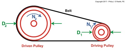
    Last time we saw how pulley diameter governs speed in engineering scenarios which make use of a belt and pulley system.   Today we’ll see how this phenomenon is defined mathematically through application of the Pulley Speed Ratio Formula, which enables precise pulley diameters to be calculated to achieve specific rotational speeds.   Today we’ll apply this Formula to a scenario involving a building’s ventilating system.

    The Pulley Speed Ratio Formula is,

                                                D1 × N1 =  D2 × N2                             (1)

where, D1 is the diameter of the driving pulley and D2 the diameter of the driven pulley.

A Pulley Speed Ratio Formula Application

A Pulley Speed Ratio Formula Application


The pulleys’ rotational speeds are represented by N1 and N2,  and are measured in revolutions per minute (RPM).

    Now, let’s apply Equation (1) to an example in which a blower must deliver a specific air flow to a building’s ventilating system.   This is accomplished by manipulating the ratios between the driven pulley’s diameter, D2, with respect to the driving pulley’s diameter, D1.   If you’ll recall from our discussion last time, when both the driving and driven  pulleys have the same diameter, the entire assembly moves at the same speed, and this would be bad for our scenario.

    An electric motor and blower impeller moving at the same speed is problematic because electric motors are designed to spin at much faster speeds than typical blower impellers in order to produce desired air flow.   If their pulleys’ diameters were the same size, it would result in an improperly working ventilating system in which air passes through the furnace heat exchanger and air conditioner cooling coils far too quickly to do an efficient job of heating or cooling.

    To bear this out, let’s suppose we have an electric motor turning at a fixed speed of 3600 RPM and a belt-driven blower with an impeller that must turn at 1500 RPM to deliver the required air flow according to the blower manufacturer’s data sheet.   The motor shaft is fitted with a pulley 3 inches in diameter.   What pulley diameter do we need for the blower to turn at the manufacturer’s required 1500 RPM?

    In this example known variables are D1 = 3 inches, N1 = 3600 RPM, and N2 = 1500 RPM.   The diameter D2 is unknown.   Inserting the known values into equation (1), we can solve for D2,

                               (3 inches) × (3600 RPM) = D2 × (1500 RPM)         (2)

Simplified, this becomes,

                                            D2 = 7.2 inches                                      (3)

    Next time we’ll see how friction affects our scenario.


Copyright 2017 – Philip J. O’Keefe, PE

Engineering Expert Witness Blog

____________________________________


Industrial Ventilation – Local Exhaust Ventilation Hoods

Sunday, April 17th, 2011
     I’m a husband who occasionally does a little vacuuming, at least of the areas I’m responsible for messing up.  It’s not one of my favorite activities, and I particularly hate it when I’m in a hurry and I don’t have enough time to move things out of the way.  That’s when an accident is prone to happen, and I end up sucking something besides dirt into the hose.  The extra work I’ve just created for myself results in my having to open up the vacuum bag and start sifting through the debris.  In the end, I sometimes end up making a bigger mess than the one I started out with.

     Vacuums are wonderful tools, when used correctly.  And when you think about it, the constituent elements of a household canister vacuum cleaner are similar to those of an industrial local exhaust ventilation system.  My home vac is comprised of five main elements, all of which most of you are familiar with:  a nozzle, hose, filter, a fan located inside the canister to provide suction, and an exhaust hole, also located within the canister, which serves to discharge newly filtered air back into the atmosphere.

     Industrial usage local exhaust ventilation systems also typically consist of five constituent elements, namely, a hood, ducts, an air cleaning device, a fan, and an exhaust stack.  Like my home vacuum its main objective is to suck something in, namely, contaminated air.  Let’s take a closer look at each of the parts.

     The hood is located at the beginning of the local exhaust ventilation system, and like your home vac’s nozzle, it’s positioned in close proximity to the area requiring cleaning.  The objective is of course to capture contaminants at the source.  Now placement of the hood within the work area is very important.  Ultimately it must be far enough away from the source of contamination so as not to interfere with the work that’s being done, yet close enough to prevent contaminants from escaping.

     Hoods that almost completely enclose the work area provide the best control of contaminants.  Trouble is, they can interfere with the work process.  That’s where a specific design of hood, known as a “capture exhaust hood” comes in handy.  This type of hood is attached to a flexible duct that resembles a super-sized vacuum cleaner hose.  This arrangement provides greater flexibility than a huge, all-encompassing hood, and it also allows the hood to be easily positioned anywhere within the workplace as necessary.

     Again, placement of a capture exhaust hood is critical to its effective operation.  Say for instance that a hood is initially positioned a mere two inches from a source of fumes, then someone comes along and bumps it.  It ends up being four inches away from the source, and now it will require around three times the amount of air volume through the system to provide the same degree of capture as it did when it was just two inches away.  If the ventilation system isn’t strong enough to draw in this extra volume of air, fumes will escape into the work area, rendering our cleanup efforts ineffective.

Next time we’ll discuss the second main component in a local exhaust ventilation system, its ductwork.

_____________________________________________