Posts Tagged ‘RPM’

Radians and the Angular Velocity of a Flywheel

Tuesday, October 10th, 2017

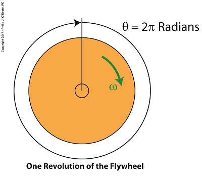
    Last time we introduced angular velocity with regard to flywheels and how a fixed point riding piggyback on a moving flywheel travels the same circular path as its host at a pace that’s measured in units of degrees per second.   Today we’ll introduce another unit of measure, the radian, and see how it’s uniquely used to measure angles of circular motion in units of radians per second.

Radians and the Angular Velocity of a Flywheel

 Radians and the Angular Velocity of a Flywheel


    Back in elementary school we worked with protractors and measured angles in degrees, and we were all too familiar with the fact that the average protractor maxed out at 180, or half the degrees present in a complete circle.   But in the grownup worlds of physics and engineering, angles of circular motion are measured in units called radians, an international standard equal to 57.3 degrees that’s used to measure objects rotating in circular motion.

    If we divide a circle’s value of 360 degrees by the 57.3 degrees that represent a radian, we find there are 6.28 radians in a circle, and oddly enough, it just so happens that 6.28 is equal to 2 × π.   Anyone who stayed awake during math class can’t help but remember that π represents a constant value of 3.14, a number that pops up anytime you divide the circumference of a circle by its diameter.   No matter the circle’s size, π will always result when you perform this operation.

   Applying these facts to radians, we find that during one complete revolution of a flywheel the measure of the angle θ increases from 0 radians to 2π radians.

    Suppose we have a flywheel spinning at N revolutions per minute, or RPMs.   To calculate the angular velocity, ω, of any point on the flywheel, or the whole wheel for that matter, we use the following formula which provides an answer in radians per second,

ω = [2 × π × N ] ÷ 60 seconds/minute                             (1)

    If a flywheel spins at 3000 RPM, its angular velocity is calculated as,

ω = [2 × π × (3000 RPM)] ÷ 60 seconds/minute               (2)

ω = 314.16 radians/second                                             (3)

    Next time we’ll see how angular velocity is used to determine the kinetic energy contained within a flywheel.


Copyright 2017 – Philip J. O’Keefe, PE

Engineering Expert Witness Blog

____________________________________


A Pulley Speed Ratio Formula Application

Friday, April 21st, 2017

    Last time we saw how pulley diameter governs speed in engineering scenarios which make use of a belt and pulley system.   Today we’ll see how this phenomenon is defined mathematically through application of the Pulley Speed Ratio Formula, which enables precise pulley diameters to be calculated to achieve specific rotational speeds.   Today we’ll apply this Formula to a scenario involving a building’s ventilating system.

    The Pulley Speed Ratio Formula is,

                                                D1 × N1 =  D2 × N2                             (1)

where, D1 is the diameter of the driving pulley and D2 the diameter of the driven pulley.

A Pulley Speed Ratio Formula Application

A Pulley Speed Ratio Formula Application


The pulleys’ rotational speeds are represented by N1 and N2,  and are measured in revolutions per minute (RPM).

    Now, let’s apply Equation (1) to an example in which a blower must deliver a specific air flow to a building’s ventilating system.   This is accomplished by manipulating the ratios between the driven pulley’s diameter, D2, with respect to the driving pulley’s diameter, D1.   If you’ll recall from our discussion last time, when both the driving and driven  pulleys have the same diameter, the entire assembly moves at the same speed, and this would be bad for our scenario.

    An electric motor and blower impeller moving at the same speed is problematic because electric motors are designed to spin at much faster speeds than typical blower impellers in order to produce desired air flow.   If their pulleys’ diameters were the same size, it would result in an improperly working ventilating system in which air passes through the furnace heat exchanger and air conditioner cooling coils far too quickly to do an efficient job of heating or cooling.

    To bear this out, let’s suppose we have an electric motor turning at a fixed speed of 3600 RPM and a belt-driven blower with an impeller that must turn at 1500 RPM to deliver the required air flow according to the blower manufacturer’s data sheet.   The motor shaft is fitted with a pulley 3 inches in diameter.   What pulley diameter do we need for the blower to turn at the manufacturer’s required 1500 RPM?

    In this example known variables are D1 = 3 inches, N1 = 3600 RPM, and N2 = 1500 RPM.   The diameter D2 is unknown.   Inserting the known values into equation (1), we can solve for D2,

                               (3 inches) × (3600 RPM) = D2 × (1500 RPM)         (2)

Simplified, this becomes,

                                            D2 = 7.2 inches                                      (3)

    Next time we’ll see how friction affects our scenario.


Copyright 2017 – Philip J. O’Keefe, PE

Engineering Expert Witness Blog

____________________________________


Gear Reduction Worked Backwards

Sunday, March 9th, 2014

      Last time we saw how a gear reduction does as its name implies, reduces the speed of the driven gear with respect to the driving gear within a gear train.   Today we’ll see how to work the problem in reverse, so to speak, by determining how many teeth a driven gear must have within a given gear train to operate at a particular desired revolutions per minute (RPM).

      For our example we’ll use a gear train whose driving gear has 18 teeth.  It’s mounted on an alternating current (AC) motor turning at 3600 (RPM).   The equipment it’s attached to requires a speed of 1800 RPM to operate correctly.   What number of teeth must the driven gear have in order to pull this off?   If you’ve identified this to be a word problem, you’re correct.

Machine Design Expert Witness

      Let’s first review the gear ratio formulas introduced in my previous two articles:

R = nDriving ÷ nDriven             (1)

R = NDriven ÷ NDriving             (2)

      Our word problem provides us with enough information so that we’re able to use Formula (1) to calculate the gear ratio required:

R = nDriving ÷ nDriven = 3600 RPM ÷ 1800 RPM = 2

      This equation tells us that to reduce the speed of the 3600 RPM motor to the required 1800 RPM, we need a gear train with a gear ratio of 2:1.   Stated another way, for every two revolutions of the driving gear, we must have one revolution of the driven gear.

      Now that we know the required gear ratio, R, we can use Formula (2) to determine how many teeth the driven gear must have to turn at the required 1800 RPM:

R = 2 = NDriven ÷ NDriving

2 = NDriven ÷ 18 Teeth

NDriven = 2 × 18 Teeth = 36 Teeth

      The driven gear requires 36 teeth to allow the gear train to operate equipment properly, that is to say, enable the gear train it’s attached to provide a speed reduction of 1800 RPM, down from the 3600 RPM that is being put out from the driving gear.

      But gear ratio isn’t just about changing speeds of the driven gear relative to the driving gear.   Next time we’ll see how it works together with the concept of torque, thus enabling small motors to do big jobs.


_______________________________________

Gear Ratio Formulas

Sunday, February 23rd, 2014

      Last time we introduced a way to convert individual gear speeds in relation to one another within a gear train by employing a conversion tool known as the gear ratio.    Today we’ll introduce the gear ratio formulas, of which there are two types.

Mechanical Engineering Expert Witness

      The first formula for determining gear ratio is based on knowing the driving gear revolutions per minute (RPM), notated as nDriving, and the driven gear RPM, nDriven.     Given that knowledge we can calculate the gear ratio, R, that exists between them by the formula:

R = nDriving ÷ nDriven             (1)

      The other way to determine gear ratio, R, is by knowing the number of teeth on both the driving gear, NDriving, and the driven gear, NDriven.    That’s right, it all boils down to simply counting the number of teeth on each gear.  In this instance the gear ratio is calculated by the following formula:

R = NDriven ÷ NDriving             (2)

      Equations (1) and (2) may look virtually identical, but they’re not.    In mechanical engineering calculations, lower case n is typically used to denote the RPM of rotating objects such as shafts, wheels, pulleys, and gears.    Upper case N is typically used to denote the number of teeth on a gear.

      Next time we’ll see how to manipulate these two equations so as to arrive at a particular gear ratio.

_______________________________________