|
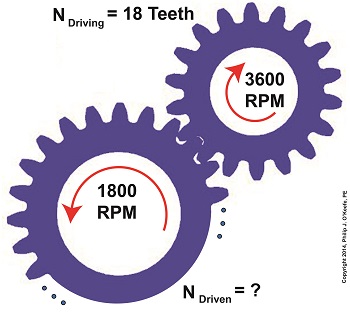
Last time we saw how a gear reduction does as its name implies, reduces the speed of the driven gear with respect to the driving gear within a gear train. Today we’ll see how to work the problem in reverse, so to speak, by determining how many teeth a driven gear must have within a given gear train to operate at a particular desired revolutions per minute (RPM). For our example we’ll use a gear train whose driving gear has 18 teeth. It’s mounted on an alternating current (AC) motor turning at 3600 (RPM). The equipment it’s attached to requires a speed of 1800 RPM to operate correctly. What number of teeth must the driven gear have in order to pull this off? If you’ve identified this to be a word problem, you’re correct. Let’s first review the gear ratio formulas introduced in my previous two articles: R = nDriving ÷ nDriven (1) R = NDriven ÷ NDriving (2) Our word problem provides us with enough information so that we’re able to use Formula (1) to calculate the gear ratio required: R = nDriving ÷ nDriven = 3600 RPM ÷ 1800 RPM = 2 This equation tells us that to reduce the speed of the 3600 RPM motor to the required 1800 RPM, we need a gear train with a gear ratio of 2:1. Stated another way, for every two revolutions of the driving gear, we must have one revolution of the driven gear. Now that we know the required gear ratio, R, we can use Formula (2) to determine how many teeth the driven gear must have to turn at the required 1800 RPM: R = 2 = NDriven ÷ NDriving 2 = NDriven ÷ 18 Teeth NDriven = 2 × 18 Teeth = 36 Teeth The driven gear requires 36 teeth to allow the gear train to operate equipment properly, that is to say, enable the gear train it’s attached to provide a speed reduction of 1800 RPM, down from the 3600 RPM that is being put out from the driving gear. But gear ratio isn’t just about changing speeds of the driven gear relative to the driving gear. Next time we’ll see how it works together with the concept of torque, thus enabling small motors to do big jobs.
_______________________________________ |
Posts Tagged ‘machine design expert witness’
Gear Reduction Worked Backwards
Sunday, March 9th, 2014Gear Terminology
Sunday, January 5th, 2014|
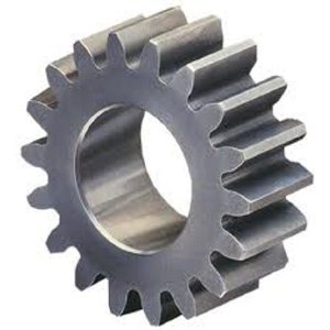
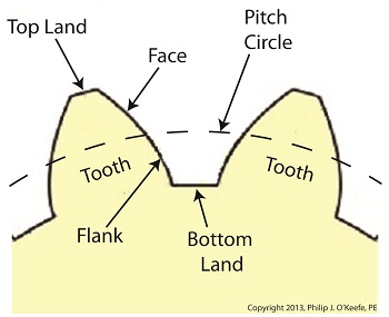
Last time we reviewed the ancient origins of gears and saw how they’ve been around a lot longer than most people realize. Now let’s familiarize ourselves with the terminology of modern gears by taking a look at the most basic and commonly used gear construction, the spur gear. A spur gear is shown below, so named due to its resemblance to spurs commonly found attached to horse riding boots. At their most basic gears are wheels containing many projections which resemble teeth. These teeth are equally spaced around the wheel’s circumference and are designed to mesh, or fit together, with the teeth of other like gears. Looking more closely at the teeth of a modern spur gear, we see they have a rather complex and peculiar curved shape, along with their own terminology. There’s a pitch circle that intersects each gear tooth between the root of the tooth, or bottom land, and the tip of the tooth, or top land. Above the pitch circle each tooth side bears a face. Below the pitch circle and under each face is a flank. Spur gear teeth don’t necessarily have to have this shape. All that’s required is that the teeth fit together in such a way so as to permit fluid interaction between them as they rotate. As a matter of fact, some primitive gears consisted of wooden wheels with teeth made of wooden pegs. These pegs were inserted into evenly spaced holes which were drilled around the circumference of the wheel. The wooden pegs of each wheel would mesh with one another, and when one gear wheel was caused to rotate, its pegs would press against the pegs of the other gear, making it rotate along with it. So if simple pegs worked well enough, then why are modern gear teeth so specifically shaped? We’ll see why next time when we join gears together to form a gear train. ________________________________________ |


