|
We’ve been working towards a general understanding of how gear trains work, and today we’ll solve a final piece of the puzzle when we identify how increased gear train torque is gained at the expense of gear train speed. Last time we developed a mathematical relationship between the torque, T, and the rotational speed, n, of the driving and driven gears in a simple gear train. This is represented by equation (8): TDriven ÷ TDriving = nDriving ÷ nDriven (8) For the purpose of our example we’ll assume that the driving gear is mounted to an electric motor shaft spinning at 100 revolutions per minute (RPM) and which produces 50 inch pounds of torque. Previous lab testing has determined that we require a torque of 100 inch pounds to properly run a piece of machinery that’s powered by the motor, and we’ve decided that the best way to get the required torque is not to employ a bigger, more powerful motor, but rather to install a gear train and manipulate its gear sizes until the desired torque is obtained. We know that using this approach will most likely affect the speed of our operation, and we want to determine how much speed will be compromised. So if the torque on the driven gear needs to be 100 inch pounds, then what will be the corresponding speed of the driven gear? To answer this question we’ll insert the numerical information we’ve been provided into equation (8). Doing so we arrive at the following: TDriven ÷ TDriving = nDriving ÷ nDriven (100 inch pounds) ÷ (50 inch pounds) = (100 RPM) ÷ nDriven 2 = (100 RPM) ÷ nDriven nDriven = (100 RPM) ÷ 2 = 50 RPM This tells us that in order to meet our torque requirement of 100 inch pounds, the gear train motor’s speed must be reduced from 100 RPM to 50 RPM, which represents a 50% reduction in speed, hence the tradeoff. This wraps up our blog series on gears and gear trains. Next time we’ll move on to a new topic: Galileo’s experiments with falling objects.
_______________________________________
|
Posts Tagged ‘pitch circle’
Determining the Gear Train Tradeoff of Torque vs. Speed, Part Three
Wednesday, August 27th, 2014Determining Torque Within a Gear Train
Monday, June 30th, 2014|
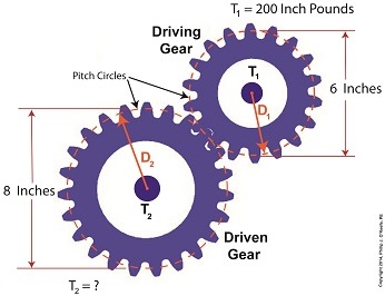
Last time we set up an example where an electric motor is connected to a lathe via a gear train. Today we’ll take the numerical values present on that gear train and plug them into the torque ratio equation we’ve been working with for the past few blogs. In the illustration below the electric motor exerts 200 inch pounds of torque upon the driving gear. The driving gear pitch circle diameter is 6 inches, while the driven gear pitch circle diameter is 8 inches. It’s been determined through previous lab testing that the lathe we’ll be using requires at least 275 inch pounds of torque to be exerted upon the driven gear shaft in order to operate properly. Will the gear train shown below meet this requirement? First, a review of the torque ratio equation: T1 ÷ T2 = D1 ÷ D2 Now we’ll crunch numbers. T1 is equal to 200 inch pounds, D1 is equal to 3 inches (pitch radius equals pitch diameter divided by two), and D2 is equal to 4 inches. This gives us: (200 inch pounds) ÷ T2 = (3 inches) ÷ (4 inches) T2 = (200 inch pounds) ÷ (0.75) = 266.67 inch pounds So, does the gear train as presented here supply enough torque to power the lathe properly? No, it does not. It provides only 266.67 inch pounds, not the 275 inch pounds of torque required. Next time we’ll see how to manipulate gear sizes within a gear train in order to meet a given torque requirement. _______________________________________
|
Equating Torques and Pitch Circle Radii Within a Gear Train
Thursday, May 29th, 2014|
Last time we developed torque equations for the driving and driven gears within a simple gear train. They are, T1 = D1 × F T2 = D2 × F where, T1 and T2 are the driving and driven gear torques, D1 and D2 are the driving and driven gear pitch radii, and F is the resultant Force vector, the common factor between the two equations. Now we’ll combine these two equations relative to F to arrive at a single equation which equates the torques and pitch circle radii of the driving and driven gears in the gear train. This type of computation is commonly used to design gear trains to ensure they perform at a given level. As a first step we’ll use algebra to rearrange terms and place the two equations equal to F. First we’ll do it for the driving gear, dividing both sides of the equation by the pitch circle radius, D1. T1 ÷ D1 = D1 ÷ D1 × F T1 ÷ D1= 1 × F F = T1 ÷ D1 In a similar fashion, we’ll do it for the driven gear by dividing both sides of the equation by the pitch circle radius, D2. T2 = D2 × F → F = T2 ÷ D2 Since F is the common term between the two equations, we can set them up as equal to each other, F = T1 ÷ D1 = T2 ÷ D2 which means that, T1 ÷ D1 = T2 ÷ D2 Next time we’ll see how to use this equation to manipulate our gear train so that it acts as a torque converter by increasing T2 with respect to T1 and the ratio of D1 to D2, thus providing a mechanical advantage to the electric motor the gear train is attached to. _______________________________________ |
Gear Train Torque Equations
Thursday, May 22nd, 2014|
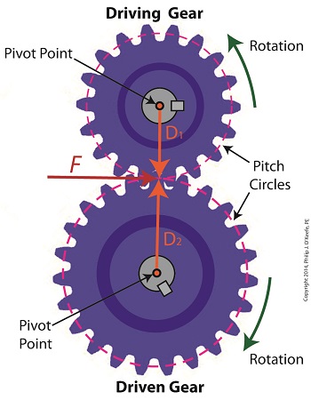
In our last blog we mathematically linked the driving and driven gear Force vectors to arrive at a single common vector F, known as the resultant Force vector. This simplification allows us to achieve common ground between F and the two Distance vectors of our driving and driven gears, represented as D1 and D2. We can then use this commonality to develop individual torque equations for both gears in the train. In this illustration we clearly see that the Force vector, F, is at a 90º angle to the two Distance vectors, D1 and D2. Let’s see why this angular relationship between them is crucial to the development of torque calculations. First a review of the basic torque formula, presented in a previous blog, Torque = Distance × Force × sin(ϴ) By inserting D1, F, and ϴ = 90º into this formula we arrive at the torque calculation, T1 , for the driving gear in our gear train: T1 = D1 × F × sin(90º) From a previous blog in this series we know that sin(90º) = 1, so it becomes, T1 = D1 × F By inserting D2, F, and ϴ = 90º into the torque formula, we arrive at the torque calculation, T2 , for the driven gear: T2 = D2 × F × sin(90º) T2 = D2 × F × 1 T2 = D2 × F Next week we’ll combine these two equations relative to F, the common link between them, and obtain a single equation equating the torques and pitch circle radii of the driving and driven gears in the gear train. _______________________________________ |
Meshed Gear Teeth and Their Point of Contact
Monday, January 27th, 2014|
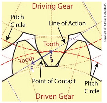
Last time we learned that the geometric shape specific to spur gear teeth is known as an involute profile. Today we’ll look at the geometry behind this profile and the very specific place at which gear teeth meet, known as the point of contact. The transmission of mechanical energy between meshed gears may seem on its face to be straightforward, after all their gears are interlaced and interact with one another. But their interaction involves some rather complex geometry, because forces are directed in a peculiar fashion between the teeth of the driving and driven gears. Let’s consider the following illustration to get a better understanding.
As we learned previously in this series, the pitch circle of a gear is an imaginary arc passing through each tooth between their top and bottom lands. The pitch circles of the driving and driven gears are represented by heavy red dashed lines in the illustration. To ensure proper alignment and smooth action between gear teeth during rotation, the gears are spaced so that their pitch circles just meet but never intersect. This specific point is known as the point of contact. It is the only point at which gears will come into actual physical contact with one another, and it provides just enough contact so that when the driving gear turns in one direction, say clockwise, its teeth exert pressure upon the driven gear teeth, forcing it to move in the opposite direction, counterclockwise. The forces which come into play at the point of contact are represented in the illustration by a black dot with oppositional blue arrows extending from it. These arrows represent the opposing mechanical forces, F1 and F2 , which act upon the teeth when they make contact. We’ll learn more about the effect of those forces next time when we follow a locomotive from a stationary position into one of movement.
_______________________________________ |
Gear Terminology
Sunday, January 5th, 2014|
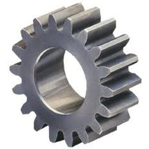
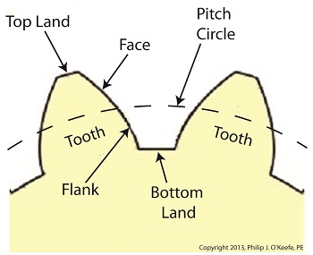
Last time we reviewed the ancient origins of gears and saw how they’ve been around a lot longer than most people realize. Now let’s familiarize ourselves with the terminology of modern gears by taking a look at the most basic and commonly used gear construction, the spur gear. A spur gear is shown below, so named due to its resemblance to spurs commonly found attached to horse riding boots. At their most basic gears are wheels containing many projections which resemble teeth. These teeth are equally spaced around the wheel’s circumference and are designed to mesh, or fit together, with the teeth of other like gears. Looking more closely at the teeth of a modern spur gear, we see they have a rather complex and peculiar curved shape, along with their own terminology. There’s a pitch circle that intersects each gear tooth between the root of the tooth, or bottom land, and the tip of the tooth, or top land. Above the pitch circle each tooth side bears a face. Below the pitch circle and under each face is a flank. Spur gear teeth don’t necessarily have to have this shape. All that’s required is that the teeth fit together in such a way so as to permit fluid interaction between them as they rotate. As a matter of fact, some primitive gears consisted of wooden wheels with teeth made of wooden pegs. These pegs were inserted into evenly spaced holes which were drilled around the circumference of the wheel. The wooden pegs of each wheel would mesh with one another, and when one gear wheel was caused to rotate, its pegs would press against the pegs of the other gear, making it rotate along with it. So if simple pegs worked well enough, then why are modern gear teeth so specifically shaped? We’ll see why next time when we join gears together to form a gear train. ________________________________________ |
