|
We’ve been working towards a general understanding of how gear trains work, and today we’ll solve a final piece of the puzzle when we identify how increased gear train torque is gained at the expense of gear train speed. Last time we developed a mathematical relationship between the torque, T, and the rotational speed, n, of the driving and driven gears in a simple gear train. This is represented by equation (8): TDriven ÷ TDriving = nDriving ÷ nDriven (8) For the purpose of our example we’ll assume that the driving gear is mounted to an electric motor shaft spinning at 100 revolutions per minute (RPM) and which produces 50 inch pounds of torque. Previous lab testing has determined that we require a torque of 100 inch pounds to properly run a piece of machinery that’s powered by the motor, and we’ve decided that the best way to get the required torque is not to employ a bigger, more powerful motor, but rather to install a gear train and manipulate its gear sizes until the desired torque is obtained. We know that using this approach will most likely affect the speed of our operation, and we want to determine how much speed will be compromised. So if the torque on the driven gear needs to be 100 inch pounds, then what will be the corresponding speed of the driven gear? To answer this question we’ll insert the numerical information we’ve been provided into equation (8). Doing so we arrive at the following: TDriven ÷ TDriving = nDriving ÷ nDriven (100 inch pounds) ÷ (50 inch pounds) = (100 RPM) ÷ nDriven 2 = (100 RPM) ÷ nDriven nDriven = (100 RPM) ÷ 2 = 50 RPM This tells us that in order to meet our torque requirement of 100 inch pounds, the gear train motor’s speed must be reduced from 100 RPM to 50 RPM, which represents a 50% reduction in speed, hence the tradeoff. This wraps up our blog series on gears and gear trains. Next time we’ll move on to a new topic: Galileo’s experiments with falling objects.
_______________________________________
|
Posts Tagged ‘gear shaft’
Determining the Gear Train Tradeoff of Torque vs. Speed, Part Three
Wednesday, August 27th, 2014How to Increase Gear Train Torque
Thursday, July 10th, 2014|
Last week we worked with a gear train equation and found that the gears under consideration were not sized properly to run a lathe. Today we’ll increase the gear train torque and solve that problem. How do we manipulate things to obtain the 275 inch pounds of torque required to drive the lathe? Last week we tried using a driven gear with a diameter of 8 inches and found that to be insufficient in size. So today the first thing we’ll try is a bigger driven gear, one with a pitch diameter of 8.5 inches. That’s 0.5 inches larger in diameter than the gear used in last week’s equation, and this just so happens to be the next size up in the gear manufacturer’s catalog. As we did last week, we’ll begin our calculations with the torque ratio equation: T1 ÷ T2 = D1 ÷ D2 We’ll use the same values as last week for T1, and D1, 200 inch pounds and 3 inches respectively, but we’ll increase the new value for D2, the driven gear pitch radius, to 4.25 inches (the new pitch diameter divided by two). Inserting these values into the torque equation, the only variable remaining without a value is torque T2. Let’s determine that value now by using algebra to rearrange terms. (200 inch pounds) ÷ T2 = (3 inches) ÷ (4.25 inches) (200 inch pounds) ÷ T2 = 0.70 T2 = (200 inch pounds) ÷ (0.70) = 283.33 inch pounds The value of T2 is found to be 283.33 inch pounds, which meets the torque requirement required to run the lathe. We were able to arrive at this torque by simply increasing the size of the driven gear relative to the size of the driving gear. In the world of Newtonian physics, this is a rather straightforward arrangement. It all boils down to this simple dynamic: When the motor’s force is acting upon a wider gear, the force is located a longer distance from the center of the driving gear shaft, which results in more torque on the shaft. As borne out by the example provided today, the larger the driven gear is in comparison to the driving gear, the more the gear train amplifies the torque that’s delivered by the motor. The principle at play here is exactly the same as that presented in a previous blog article where, for a given force exerted upon a wrench, torque was increased by simply increasing the length of the wrench handle. Some of you may be wondering why we didn’t just use a bigger, more powerful motor to begin with, thereby eliminating the need for a gear train and all the calculations we’ve been running? We’ll see why that’s not always possible or practical next time. _______________________________________
|
Gear Train Torque Equations
Thursday, May 22nd, 2014|
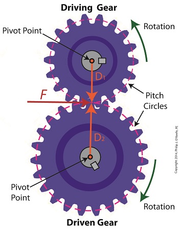
In our last blog we mathematically linked the driving and driven gear Force vectors to arrive at a single common vector F, known as the resultant Force vector. This simplification allows us to achieve common ground between F and the two Distance vectors of our driving and driven gears, represented as D1 and D2. We can then use this commonality to develop individual torque equations for both gears in the train. In this illustration we clearly see that the Force vector, F, is at a 90º angle to the two Distance vectors, D1 and D2. Let’s see why this angular relationship between them is crucial to the development of torque calculations. First a review of the basic torque formula, presented in a previous blog, Torque = Distance × Force × sin(ϴ) By inserting D1, F, and ϴ = 90º into this formula we arrive at the torque calculation, T1 , for the driving gear in our gear train: T1 = D1 × F × sin(90º) From a previous blog in this series we know that sin(90º) = 1, so it becomes, T1 = D1 × F By inserting D2, F, and ϴ = 90º into the torque formula, we arrive at the torque calculation, T2 , for the driven gear: T2 = D2 × F × sin(90º) T2 = D2 × F × 1 T2 = D2 × F Next week we’ll combine these two equations relative to F, the common link between them, and obtain a single equation equating the torques and pitch circle radii of the driving and driven gears in the gear train. _______________________________________ |


