|
Last week we worked with a gear train equation and found that the gears under consideration were not sized properly to run a lathe. Today we’ll increase the gear train torque and solve that problem. How do we manipulate things to obtain the 275 inch pounds of torque required to drive the lathe? Last week we tried using a driven gear with a diameter of 8 inches and found that to be insufficient in size. So today the first thing we’ll try is a bigger driven gear, one with a pitch diameter of 8.5 inches. That’s 0.5 inches larger in diameter than the gear used in last week’s equation, and this just so happens to be the next size up in the gear manufacturer’s catalog. As we did last week, we’ll begin our calculations with the torque ratio equation: T1 ÷ T2 = D1 ÷ D2 We’ll use the same values as last week for T1, and D1, 200 inch pounds and 3 inches respectively, but we’ll increase the new value for D2, the driven gear pitch radius, to 4.25 inches (the new pitch diameter divided by two). Inserting these values into the torque equation, the only variable remaining without a value is torque T2. Let’s determine that value now by using algebra to rearrange terms. (200 inch pounds) ÷ T2 = (3 inches) ÷ (4.25 inches) (200 inch pounds) ÷ T2 = 0.70 T2 = (200 inch pounds) ÷ (0.70) = 283.33 inch pounds The value of T2 is found to be 283.33 inch pounds, which meets the torque requirement required to run the lathe. We were able to arrive at this torque by simply increasing the size of the driven gear relative to the size of the driving gear. In the world of Newtonian physics, this is a rather straightforward arrangement. It all boils down to this simple dynamic: When the motor’s force is acting upon a wider gear, the force is located a longer distance from the center of the driving gear shaft, which results in more torque on the shaft. As borne out by the example provided today, the larger the driven gear is in comparison to the driving gear, the more the gear train amplifies the torque that’s delivered by the motor. The principle at play here is exactly the same as that presented in a previous blog article where, for a given force exerted upon a wrench, torque was increased by simply increasing the length of the wrench handle. Some of you may be wondering why we didn’t just use a bigger, more powerful motor to begin with, thereby eliminating the need for a gear train and all the calculations we’ve been running? We’ll see why that’s not always possible or practical next time. _______________________________________
|
Posts Tagged ‘wrench’
How to Increase Gear Train Torque
Thursday, July 10th, 2014Torque and Force
Tuesday, April 29th, 2014|
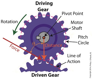
We’ve been discussing torque and how it enables more power to be available to applications such as loosening tight nuts with a wrench. Now we’ll see how those same principles apply to another application, a simple gear train. To review, the torque formula is, Torque = Distance × Force × sin(ϴ) where, Distance and Force are vector magnitudes and ϴ is the angle formed between them. Referring to the gear train illustration above, we see that Force and Distance vectors are present, just as they had been in our previous wrench/nut example. But instead of torque being created by way of force that’s applied to a wrench, things are reversed, and it’s the torque that creates the force. You see, in the wrench/nut example, the force applied to the wrench handle created torque on the nut. In our present gear train example, the torque applied to the motor shaft is created by an electric motor exerting pressure upon the motor shaft, which in turn exerts a force upon the driving gear teeth. The driving gear is also attached to this shaft, so torque causes the driving gear to rotate along with the motor. This rotation results in a force being exerted at the point where the teeth of the driving gear mesh with the teeth of the driven gear. In other words, in the wrench/nut example force created torque, while in the present example torque creates a force. The gear train has a pivot point, as there was in our wrench/nut example, but this time it’s located at the center of the motor shaft rather than at the center of a nut. The pivot point in both examples is where the action takes place. The motor’s shaft and driving gear rotate around it, just as the wrench jaws and handle rotated around the nut’s pivot point. In both examples, the Distance vectors extend out from the pivot points to meet up with the Force vector’s path. In the gear train example, this Force vector path is called a line of action, as introduced earlier in this blog series. This line of action passes through to the point where the driving and driven gear teeth mesh. The force acting upon that point causes the gears in the gear train to rotate, and as they turn mechanical energy is transferred from the motor to whatever machinery component is attached to the shaft of the driven gear. The powered component will then be able to perform useful work such as cutting lumber, mixing frosting for a cake, drilling holes in steel, or propelling vehicles. You will note that there is an angle ϴ which exists between the Distance and Force vectors. Since we have a pivot point, a Force vector, a Distance vector, and an angle ϴ, we are able to apply the torque formula to gear trains exactly as we did in our wrench/nut example. We can then use that formula to calculate how torque is transmitted between gears in the train. Next time we’ll examine the distance and force vectors in a simple gear train. _______________________________________ |
Manipulating theTorque Formula
Wednesday, April 23rd, 2014|
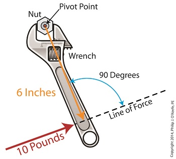
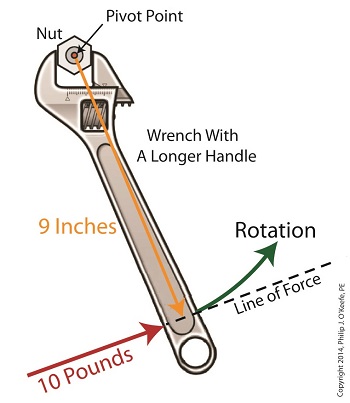
Last time we introduced the simplified formula for torque: Torque = Distance × Force Today we’ll manipulate it by way of our wrench and nut example to get the torque that we need to loosen a tight nut. By inserting the numerical values of our illustration into the torque formula, it becomes: Torque = 6 inches × 10 pounds = 60 inch-pounds Inch-pounds may be terminology you’re unfamiliar with, but this notation arises from the fact that torque values are always represented by units of distance and force separated by a hyphen, in our case inch-pounds. This just means that distance and force were multiplied together to calculate torque. In order to manipulate the value for torque all that needs to be done is change either or both numerical values for Distance and Force. Increasing either or both factors produces higher torque, decreasing them less torque. Why manipulate torque? To provide us with a mechanical advantage. Suppose we have a rusted nut that we’re trying to move with a wrench that has a 6 inch handle, and the 10 pounds of force employed by the muscles in our arm just won’t budge it. Put another way, 60 inch-pounds of torque is insufficient to rotate the nut. It’s clear we must increase torque to get things going. Let’s do so by increasing either of the vector magnitudes. First we’ll try increasing the magnitude of the force vector. Instead of simply pushing hard on the wrench handle with our arm, let’s say we push extra hard. The average man can do a bicep curl of between 30 to 40 pounds, but we haven’t been going to the gym lately and we’re really out of shape. So try as we will, we just can’t muster up the bicep strength to apply more than 10 pounds of force to the wrench handle. It’s clear that this approach to increasing torque upon the nut isn’t going to work. The other way to increase torque is to increase the length of the distance vector. We’ll need a wrench with a longer handle, say 9 inches. By using a wrench with a longer handle we have increased the magnitude of the distance vector from 6 to 9 inches. The torque formula becomes: Torque = 9 inches × 10 pounds = 90 inch-pounds Eureka! The longer handle has provided us with the mechanical advantage needed to increase torque to 90 inch-pounds, thereby overcoming our muscular shortcomings and breaking the nut free. In summary, since torque is the product of the magnitudes of the distance and force vectors, we can increase torque by either increasing the magnitude of the force vector, or as in our example, by increasing the magnitude of the distance vector. Next time we’ll see how to apply the principles of torque to a real world situation involving gear trains in which we need to obtain a mechanical advantage. _______________________________________ |
Torque Formula Symplified
Wednesday, April 2nd, 2014|
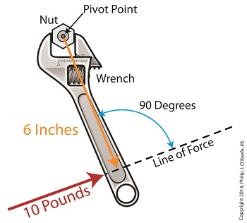
Last time we introduced the mathematical formula for torque, which is most simply defined as a measure of how much a force acting upon an object causes that object to rotate around a pivot point. When manipulated, torque can produce a mechanical advantage in gear trains and tools, which we’ll see later. The formula is: Torque = Distance × Force × sin(ϴ) We learned that the factors Distance and Force are vectors, and sin(ϴ) is a trigonometric function of the angle ϴ which is formed between their two vectors. Let’s return to our wrench example and see how the torque formula works. Vectors have both a magnitude, that is, a size or extent, and a direction, and they are typically represented in physics and engineering problems by straight arrows. In our illustration the vector for distance is represented by an orange arrow, while the vector for force is represented by a red arrow. The orange distance vector has a magnitude of 6 inches, while the red force vector has a magnitude of 10 pounds, which is being supplied by the user’s arm muscle manipulating the nut. That muscle force follows a path from the arm to the pivot point located at the center of the nut, a distance of 6 inches. Vector arrows point in a specific direction, a direction which is indicative of the way in which the vectors’ magnitudes — in our case inches of distance vs. pounds of force — are oriented with respect to one another. In our illustration the orange distance vector points away from the pivot point. This is according to engineering and physics convention, which dictates that, when a force vector is acting upon an object to produce a torque, the distance vector always points from the object’s pivot point to the line of force associated with the force vector. The angle, ϴ, that is formed between the two vectors in our example is 90 degrees, as measured by any common, ordinary protractor. Next we must determine the trigonometric value for sin(ϴ). This is easily accomplished by simply entering “90” into our calculator, then pressing the sin button. An interesting fact is that when the angle ϴ ranges anywhere between 0 and 90 degrees, the values for sin(ϴ) always range between 0 and 1. To see this in action enter any number between 0 and 90 into a scientific calculator, then press the sin button. For our angle of 90 degrees we find that, sin(90) = 1 Thus the formula for torque in our example, because the sin(ϴ) is equal to 1, simply becomes the product of the magnitudes of the Distance and Force vectors: Torque = Distance × Force × sin(90) Torque = Distance × Force × 1 Torque = Distance × Force Next time we’ll insert numerical values into the equation and see how easily torque can be manipulated. _______________________________________ |
Achieving Mechanical Advantage Through Torque
Wednesday, March 19th, 2014|
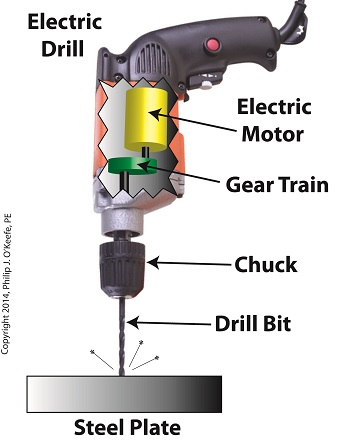
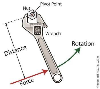
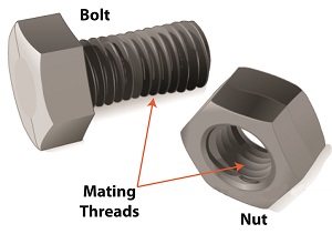
Last time we saw how gear train ratios allow us to change the speed of the driven gear relative to the driving gear. Today we’ll extend this concept further and see how gear trains are used to amplify the mechanical power output of small motors and in so doing create a mechanical advantage, an advantage made possible through the physics of torque. Below is an ordinary electric drill. Let’s see what’s inside its shell. There’s a whole lot of mechanical advantage at work here, giving the drill’s small motor the ability to perform big jobs. A motor and gear train are housed within the drill itself. The motor shaft is coupled to the chuck shaft via the gear train, and by extension, the drill bit. A chuck holds the drill bit in place. It’s the drill’s gear train that provides the small motor with the mechanical advantage necessary for this hand-held power tool to perform the big job of cutting through a thick steel plate. If the gear train and its properly engineered gear ratio weren’t in place and the chuck’s shaft was connected directly to the motor shaft, the motor would be overwhelmed and would stall or become damaged. Either way, the work won’t get done. To understand how operations like these can be performed, we must first familiarize ourselves with the physics concept of torque. Torque allows us to analyze the rotational forces acting upon rotating objects, such as gears in a gear train and wrenches on nuts and bolts. Manipulating torque allows us to achieve a physical advantage when rotating objects around a pivot point. Let’s illustrate this by using a wrench to turn a nut. The nut is fastened to the bolt with threads, interconnecting spiral grooves formed on both the inside of the nut and the outside of the bolt. A wrench is used to loosen and tighten the nut by rotating it on its mating threads. The nut itself rotates about a pivot point which lies at its center. When you use your arm to manipulate the wrench you apply force, a force which is transmitted at a distance from the pivot point. This in turn creates a torque on the nut. In other words, torque is a function of the force acting upon the handle relative to its distance from the pivot point at the center of the nut. Torque can be increased by changing one or both of its acting factors, force and distance. We’ll see how next time when we examine the formula for torque and manipulate it so that a weak arm can loosen even the tightest nut. _______________________________________ |
