|
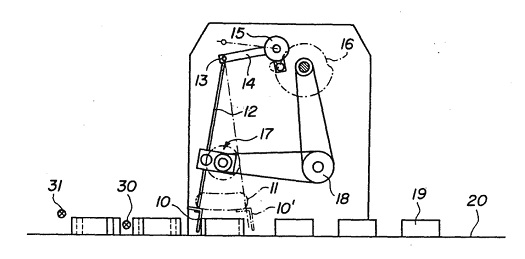
Last week I introduced this illustration as a typical patent drawing and asked if you could decipher the riddle of its functionality.
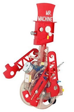
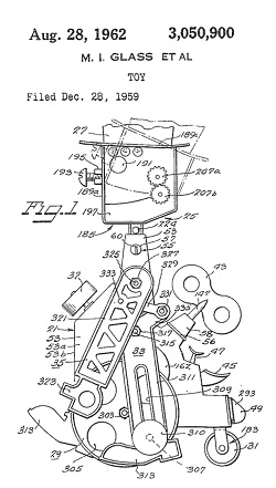
Patent drawings are static, two dimensional (2D) representations of proposed inventions which are meant to be manufactured in three dimensions (3D). As such they present a lot of complex information on a flat page. If you don’t have a clue as to what this machine is, I guarantee you’re not alone. The average person wouldn’t. There’s a bunch of lines, shapes and numbers, but what do they signify? How are they meant to all come together and operate? As a matter of fact, the average person isn’t meant to understand patent drawings. That’s because they’re not what patent courts have defined as a person of ordinary skill in the art, a peculiar term which basically means that the Average Joe or Josephine isn’t meant to be able to interpret them. Rather, the interpretation of patent drawings is left to individuals with specialized skills and training, a particular educational background and/or work experience. These individuals are typically able to view a static 2D image and visualize how the illustrated device moves, how it operates. Those said to fall within the court’s definition as having ordinary skill in the art are in fact often engineers and scientists. Since the average person does not have a background in engineering and science, it can be challenging for patent attorneys to present their cases in the courtroom, particularly when relying on 2D representations alone. That’s where animations come in. Next time we’ll use the magic of animation to transform our cryptic 2D patent illustration into a functional 3D animation of a machine whose operation is easily understood by the average person. ___________________________________________ |
Posts Tagged ‘electrical engineer’
Patent Drawings – “Ordinary Skill in the Art”
Sunday, June 9th, 2013Determining Patent Eligibility – Part 3, What Constitutes a Machine?
Sunday, April 21st, 2013Diesel Locomotive Brakes
Sunday, June 6th, 2010|
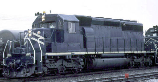
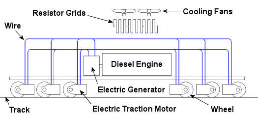
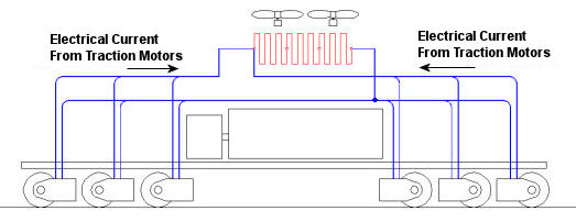
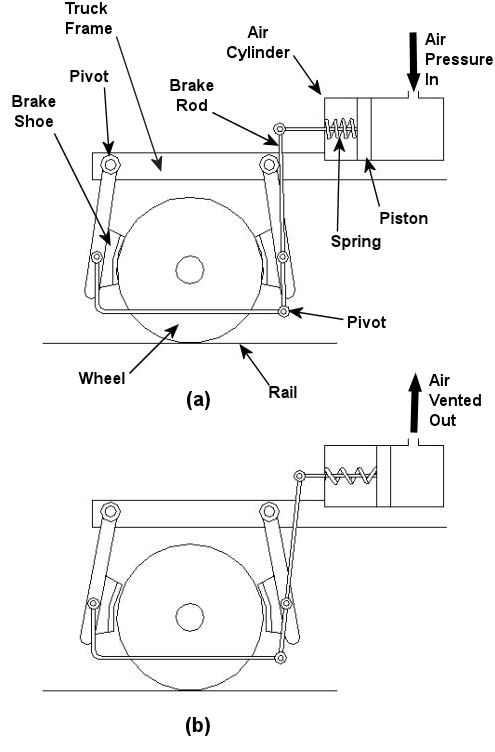
In the past few weeks we’ve taken a look at both mechanical and dynamic brakes. Now it’s time to bring the two together for unparalleled stopping performance. Have you ever wandered along a railroad track, hopping from tie to tie, daring a train to come roaring along and wondering if you could jump to safety in time? Many have, and many have lost the bet. That’s because a train, once set into motion, is one of the hardest things on Earth to bring to a stop. In this discussion, let’s focus on the locomotive. A large, six-axle variety is shown in Figure 1. Figure 1 – A Six-Axle Diesel-Electric Locomotive These massive iron horses are known in the industry as diesel-electric locomotives, and here’s why. As Figure 2 shows, diesel-electric locomotives are powered by huge diesel engines. Their engine spins an electrical generator which effectively converts mechanical energy into electrical energy. That electrical energy is then sent from the generator through wires to electric traction motors which are in turn connected to the locomotive’s wheels by a series of gears. In the case of a six-axle locomotive, there are six traction motors all working together to make the locomotive move. So how do you get this beast to stop? Figure 2 – The Propulsion System In A Six-Axle Diesel-Electric Locomotive You probably noticed in Figure 2 that there are resistor grids and cooling fans. As long as you’re powering a locomotive’s traction motors to move a train, these grids and fans won’t come into play. It’s when you want to stop the train that they become important. That’s when the locomotive’s controls will act to disconnect the traction motor wires running from the electrical generator and reconnect them to the resistor grids as shown in Figure 3 below. Figure 3 – The Dynamic Braking System In A Six-Axle Diesel Electric Locomotive The traction motors now become generators in a dynamic braking system. These motors take on the properties of a generator, converting the moving train’s mechanical, or kinetic, energy into electrical. The electrical energy is then moved by wires to the resistor grids where it is converted to heat energy. This heat energy is removed by powerful cooling fans and released into the atmosphere. In the process the train is robbed of its kinetic energy, causing it to slow down. Now you may be thinking that dynamic brakes do all the work, and this is pretty much true, up to a point. Although dynamic brakes may be extremely effective in slowing a fast-moving train, they become increasingly ineffective as the train’s speed decreases. That’s because as speed decreases, the traction motors spin more slowly, and they convert less kinetic energy into electrical energy. In fact, below speeds of about 10 miles per hour dynamic brakes are essentially useless. It is at this point that the mechanical braking system comes into play to bring the train to a complete stop. Let’s see how this switch from dynamic to mechanical dominance takes place. A basic mechanical braking system for locomotive wheels is shown in Figure 4. This system, also known as a pneumatic braking system, is powered by compressed air that is produced by the locomotive’s air pump. A similar system is used in the train’s railcars, employing hoses to move the compressed air from the locomotive to each car. Figure 4 – Locomotive Pneumatic Braking System In the locomotive pneumatic braking system, pressurized air enters an air cylinder. Once inside, the air bears against a spring-loaded piston, as shown in Figure 4(a). The piston moves, causing brake rods to pivot and clamp the brake shoes to the locomotive’s wheel with great force, slowing the locomotive. When you want to get the locomotive moving again, you vent the air out of the cylinder as shown in Figure 4(b). This takes the pressure off the piston, releasing the force from the brake shoes. The spring in the cylinder is now free to move the shoes away from the wheel so they can turn freely. We have now returned to the situation present in Figure 2, and the locomotive starts moving again. Next week we’ll talk about regenerative braking, a variation on the dynamic braking concept used in railway vehicles like electric locomotives and subway trains. _____________________________________________ |
Forensic Engineering Focus On Electrical Fires
Sunday, October 4th, 2009|
Property damage and loss of lives, these are often the result of fires. But did you know that one of the leading causes of fire is electricity? Residential electrical fires claim the lives of nearly 500 Americans each year and injure another 2300. Annually, these fires result in over $800 million in property losses. Approximately one third of the nearly 70,000 home electrical fires that occur each year are traceable to design and manufacturing defects in electrical products. The rest are caused by the misuse and poor maintenance of electrical products, overloaded circuits and extension cords, and incorrectly installed wiring. The three components that must be present in order for a fire to manifest and sustain itself are well known. These components make up the “Fire Triangle,” a potentially lethal combination of heat, fuel, and oxygen. If any one of these three components is missing from the triangle, a fire can’t be started or sustained. In the case of an electrical fire, it’s electricity that creates the heat component of the Fire Triangle.
The Fire Triangle How does electricity contribute to fires? One example would be an overloaded extension cord. Homeowners are sometimes unaware that extension cords must be sized appropriately for their ultimate usage. If not, they can overheat, particularly if they are damaged. Damage to cords can result from a myriad of factors, from factory production errors to kinking when heavy furniture is carelessly placed on top of them. The same principle holds true for electrical products. If their internal wiring or a component is insufficiently sized or damaged, overheating can result. If things get hot enough and there is sufficient airflow (oxygen) and combustible material (fuel) in the vicinity, then the fire triangle is complete. The fire starts internally and can soon spread to other objects in the area. Electrical arcing can occur when an energized electrical circuit is broken. For example, suppose a wire carrying current is suddenly broken in two. If the voltage is high enough, the electricity will want to continue to flow through the air across the break to form an electrical arc. If the power flowing through the arc is great enough, heat can once again complete the Fire Triangle, resulting in fire. Forensic engineering analysis of evidence collected from a fire scene often yields telltale signs of overheating due to overloaded electrical circuits or damaged wiring in components. Under close examination by an experienced professional, even the smallest strand of wire can point to the cause of an electrical fire. CSI skills aren’t only employed at crime scenes. Forensic engineers also use similar techniques to get to the true story of cause and effect. _________________________________________________________________ |
