|
Electric cars are a win-win proposition, right? They’re the solution to many if not most of our vehicle emission problems, right? They’re all good, whereas power derived from petroleum-based fuels is all bad, right? Unfortunately, just as nothing in life is all good or all bad, so goes the reality behind electric cars. Sure, they will most certainly reduce our reliance on foreign oil, which is a good thing, but they also come with some not-so-good things attached to them. Those of us who drive hybrids know that its battery must continually recharge. It is able to do this through various means, many of which take their beginnings in the power that is derived from the fossil fuels that also run the car. So, too, will the batteries that charge electric cars eventually run down, and when they do, they must be plugged into a source of electrical energy to recharge. So where does this electrical energy come from? It comes from an electric utility grid, the same grid that provides powers to our homes and businesses. And this is where the pretty picture converges upon some not so pretty elements, because the utility grid is largely fed by fossil fueled power plants that burn coal, natural gas, and, yes, even oil, the very thing we were trying to get away from when designing the concept for our electric cars. Presently, the US Department of Energy reports that 71.2 percent of our power is generated by burning fossil fuels, and ultimately this is what will be providing the power behind electric cars. We all recognize the fact that the smoke that rises from the stacks of fossil fuel plants release pollutants into the environment, and we’re trying very earnestly to do something about that. Would adding pollution control devices to them serve to curb their emissions? Yes, but they would come at a high price as these devices are extremely expensive to build, operate, and maintain. In fact, they are so expensive they would add a hefty price tag to our already high-priced electric utility bills. There’s got to be a better way to make the electricity to power a car, right? What about using alternative energy sources? We’ll explore these options next week. _________________________________________________________________ |
Archive for March, 2010
When It Comes to Energy, There’s No Free Ride
Sunday, March 28th, 2010Machine Design in Mechanical Engineering
Sunday, March 21st, 2010|
Last week we wrapped up our discussion of vibration analysis. It’s been a long time coming, but this week we’ll conclude our series on the many aspects of mechanical engineering by discussing machine design. If you’ve been with us since the beginning of the series and you’re not a mechanical engineer, I’d venture to say you’re now impressed with the wide scope of issues with which mechanical engineering is concerned. In our preceding discussions we examined some basic concepts behind statics, dynamics, kinematics, strengths of materials, material science, thermodynamics, heat transfer, fluid mechanics, and vibrations. This is the foundation of mechanical engineering know-how. But when we consider machine design as a whole, we often have to keep in mind the old cliché, “Why reinvent the wheel?” I say this because engineers have been designing machines and mechanical systems for hundreds of years. Over this time, their design accomplishments have been collected, standardized, and tabulated in engineering handbooks and product catalogs to make things easier for future generations and to eliminate redundancy of work effort. Put another way, why design nuts, bolts, pumps, heat exchangers, motors, gears, pulleys, and drive belts for a new machine when someone already designed them for similar applications in the past and they are readily available for quick purchase from suppliers? For example, suppose you had to design a machine that will be driven by an electric motor using sprockets and a roller chain. This is the same method that your bicycle employs to transfer foot power applied to the pedals back to the rear wheel, which gets you rolling. So, how do you come up with a chain that will do the job without breaking? To incorporate a sprocket and roller chain drive system into your machine design, you must first determine how much horsepower you will need to run the machine, the speed at which it must operate, and the conditions under which it will operate. You can use this information to design a chain from scratch, then test it to see if it works, then have it custom manufactured. Translation: Lots of time, effort and money expended. Or, you could get a hold of a book that’s been around since 1914, Machinery’s Handbook. This is considered by many to be one of the best mechanical engineering reference handbooks of all time. It contains tables of information that can be used to select standard, commercially available roller chains based on both horsepower and speed requirements. It also has lots of other engineering-specific information on various other machine components. Based on our example above, I think you can conclude that the fastest, most economical route to take to construction of our mechanism is to use as many standardized, commercially available components as possible. Knowing where to find information on these components and how to use them is very important to the success of your design, and this is precisely the information that you would have picked up during your final year of study towards earning a Bachelor’s Degree in Mechanical Engineering. As a student, you would have been required to take at least a few machine design courses. Well, that’s it for our series on understanding the basics of mechanical engineering. I hope you enjoyed it and it helped you to better understand the fundamentals of what mechanical engineering is all about. _________________________________________________________________
|
Vibration Analysis in Mechanical Engineering, Part II
Sunday, March 14th, 2010Vibration Analysis in Mechanical Engineering, Part I
Sunday, March 7th, 2010|
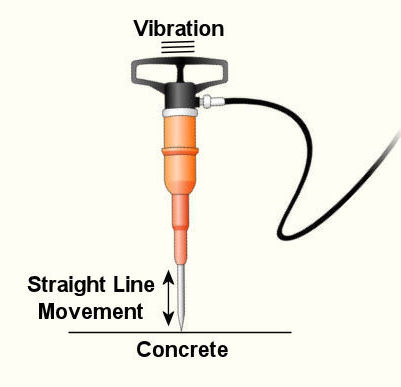
Last week we wrapped up our discussion on heat transfer. This week we’ll turn to a discussion on vibration analysis. Vibration occurs when there is physical movement of a machine part when compared to a point of reference. This physical movement can manifest in a straight line, a circle, or any way imaginable in three dimensions. The point of reference can be a guideway for a sliding part or a shaft for a rotating part. As discussed in kinetics, machine parts have mass, and when mass moves it contains kinetic energy, so it makes sense that when a part moves within a machine, the energy created can result in forces that act upon the machine as a whole. The net result is machine vibration which occurs in “sympathy” with the movement of the original mechanical part under discussion. Let’s talk about examples of vibration caused by straight line and circular motion. And what figure conjures up a better image of up-and-down straight line vibration then a jackhammer, as shown in Figure 1. This tool has a chisel which is attached to an air piston that moves up and down in a straight line, and the chisel and piston each have mass. It is the rapid up and down movement of the total mass of the device that results in concrete-breaking force. Unfortunately, those forces also vibrate back up the jackhammers shaft into the hands, arms and body of the construction worker operating it. Figure 1 – A Jackhammer
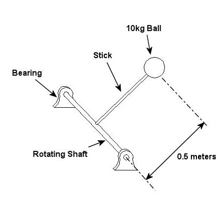
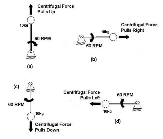
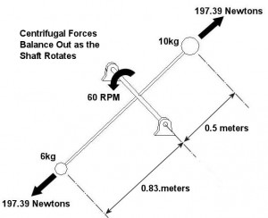
An example of vibration caused by circular movement can be found in your washing machine. Ever notice what happens when you throw one heavy object, say a throw rug, into it, and it begins the spin cycle? That “THUMP-THUMP-THUMP” sound that just won’t quit is due to the rug, now wet and congealed into a single heavy lump to one side of the agitator. It continues to spin about the center of the agitator, creating an unbalanced outward centrifugal force that keeps changing direction around its central pivot point, the agitator. This force makes the washing machine want to rock from side to side and front to back. Now imagine this situation taking place inside your washer day after day, hour after hour, every time you put a load to wash. How long do you think your washer would last under this usage? As this example illustrates, vibrations must be considered in machine design because if they are severe enough, they can cause machine parts to prematurely wear and fail. Speaking of wear and failure, you might have discovered how the tires on your car wore out prematurely and a mechanic said this happened because your shock absorbers or struts are bad. Shock absorbers and struts help to safely control, or “dampen,” vibrations in the suspension system that result when your car’s wheels roll down the highway. Without proper damping, the vibration forces can cause your tire to literally bounce down the road and grind on the pavement with each landing. Oh, yes, if the vibration is strong enough, you can even lose control of your car and end up in a crash. Unfortunately, strong vibrations do not only affect machinery, but the people that come into contact with them, often causing physical discomfort and injury. Ever heard of “white finger syndrome,” otherwise known as Raynaud’s syndrome? This painful condition, which results when vibrations impair blood flow to the fingers, causes them to tingle, feel numb, and then turn white. The longer a person uses a vibrating tool, and the faster the tool vibrates, the greater the risk. Well that’s our initial plunge into the world of vibrations. Now that we know the basics of what vibrations are and what they can do, next time we can explore how to resolve a straightforward vibration problem which often presents itself in rotating mechanisms. _________________________________________________________________ |
