|
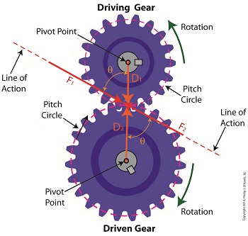
Last time we analyzed the angular relationship between the Force and Distance vectors in this simple gear train. Today we’ll discover a commonality between the two gears in this train which will later enable us to develop individual torque calculations for them. From the illustration it’s clear that the driving gear is mechanically linked to the driven gear by their teeth. Because they’re linked, force, and hence torque, is transmitted by way of the driving gear to the driven gear. Knowing this we can develop a mathematical equation to link the driving gear Force vector F1 to the driven gear Force vector F2, then use that linking equation to develop a separate torque formula for each of the gears in the train. We learned in the previous blog in this series that F1 and F2 travel in opposite directions to each other along the same line of action. As such, both of these Force vectors are situated in the same way so that they are each at an angle value ϴ with respect to their Distance vectors D1 and D2. This fact allows us to build an equation with like terms, and that in turn allows us to use trigonometry to link the two force vectors into a single equation: F = [F1 × sin(ϴ)] – [F2 × sin(ϴ)] where F is called a resultant Force vector, so named because it represents the force that results when the dead, or inert, weight that’s present in the resisting force F2 cancels out some of the positive force of F1. Next week we’ll simplify our gear train illustration and delve into more math in order to develop separate torque computations for each gear in the train. _______________________________________ |
Posts Tagged ‘vector’
The Mathematical Link Between Gears in a Gear Train
Wednesday, May 14th, 2014Distance and Force Vectors of a Simple Gear Train
Monday, May 5th, 2014|
Last time we examined how torque and force are created upon the driving gear within a simple gear train. Today we’ll see how they affect the driven gear. Looking at the gear train illustration above, we see that each gear has both distance and force vectors. We’ll call the driving gear Distance vector, D1, and the driven gear Distance vector, D2. Each of these Distance vectors extend from pivot points located at the centers of their respective gear shafts. From there they extend in opposite directions until they meet at the line of action, the imaginary line which represents the geometric path along which Force vectors F1 and F2 are aligned. As we learned last time, the Force vector, F1, results from the torque that’s created at the pivot point located at the center of the driving gear. This driving gear is mounted on a shaft that’s attached to an electric motor, the ultimate powering source behind the torque. F1 follows a path along the line of action until it meets with the driven gear teeth, where it then exerts its pushing force upon them. It’s met by Force vector F2, a resisting force, which extends along the same line of action, but in a direction opposite to that of F1. These two Force vectors butt heads, pushing back against one another. F2 is essentially a negative force manifested by the dead weight of the mechanical load of the machinery components resting upon the shaft of the driving gear. Its unmoving inertia resists being put into motion. In order for the gears in the gear train to turn, F1 must be greater than F2, in other words, it must be great enough to overcome the resistance presented by F2. With the two Force vectors pushing against each other along the line of action, the angle ϴ between vectors F2 and D2, is the same as the angle ϴ between F1 and D1. Next time we’ll use the angular relationship between these four vectors to develop torque calculations for both gears in the gear train. _______________________________________ |
Torque Formula Symplified
Wednesday, April 2nd, 2014|
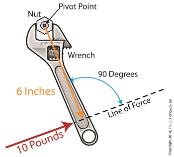
Last time we introduced the mathematical formula for torque, which is most simply defined as a measure of how much a force acting upon an object causes that object to rotate around a pivot point. When manipulated, torque can produce a mechanical advantage in gear trains and tools, which we’ll see later. The formula is: Torque = Distance × Force × sin(ϴ) We learned that the factors Distance and Force are vectors, and sin(ϴ) is a trigonometric function of the angle ϴ which is formed between their two vectors. Let’s return to our wrench example and see how the torque formula works. Vectors have both a magnitude, that is, a size or extent, and a direction, and they are typically represented in physics and engineering problems by straight arrows. In our illustration the vector for distance is represented by an orange arrow, while the vector for force is represented by a red arrow. The orange distance vector has a magnitude of 6 inches, while the red force vector has a magnitude of 10 pounds, which is being supplied by the user’s arm muscle manipulating the nut. That muscle force follows a path from the arm to the pivot point located at the center of the nut, a distance of 6 inches. Vector arrows point in a specific direction, a direction which is indicative of the way in which the vectors’ magnitudes — in our case inches of distance vs. pounds of force — are oriented with respect to one another. In our illustration the orange distance vector points away from the pivot point. This is according to engineering and physics convention, which dictates that, when a force vector is acting upon an object to produce a torque, the distance vector always points from the object’s pivot point to the line of force associated with the force vector. The angle, ϴ, that is formed between the two vectors in our example is 90 degrees, as measured by any common, ordinary protractor. Next we must determine the trigonometric value for sin(ϴ). This is easily accomplished by simply entering “90” into our calculator, then pressing the sin button. An interesting fact is that when the angle ϴ ranges anywhere between 0 and 90 degrees, the values for sin(ϴ) always range between 0 and 1. To see this in action enter any number between 0 and 90 into a scientific calculator, then press the sin button. For our angle of 90 degrees we find that, sin(90) = 1 Thus the formula for torque in our example, because the sin(ϴ) is equal to 1, simply becomes the product of the magnitudes of the Distance and Force vectors: Torque = Distance × Force × sin(90) Torque = Distance × Force × 1 Torque = Distance × Force Next time we’ll insert numerical values into the equation and see how easily torque can be manipulated. _______________________________________ |
Vectors, Sin(ϴ), and the Torque Formula
Wednesday, March 26th, 2014|
Last time we introduced a physics concept known as torque and how it, together with modified gear ratios, can produce a mechanical advantage in devices whose motors utilize gear trains. Now we’ll familiarize ourselves with torque’s mathematical formula, which involves some terminology, symbols, and concepts which you may not be familiar with, among them, vectors, and sin(ϴ). Torque = Distance × Force × sin(ϴ) In this formula, Distance and Force are both vectors. Generally speaking, a vector is a quantity that has both a magnitude — that is, any measured quantity associated with a vector, whether that be measured in pounds or inches or any other unit of measurement — and a direction. Vectors are typically represented graphically in engineering and physics illustrations by pointing arrows. The arrows are indicative of the directionality of the magnitudes involved. Sin(ϴ), pronounced sine thay-tah, is a function found within a field of mathematics known as trigonometry , which concerns itself with the lengths and angles of triangles. ϴ, or thay-tah, is a Greek symbol used to represent the angle present between the Force and Distance vectors as they interact to create torque. The value of sin(ϴ) depends upon the number of degrees in the angle ϴ. Sin(ϴ) can be found by measuring the angle ϴ, entering its value into a scientific calculator, and pressing the Sin button. We’ll dive into the math behind the vectors next time, when we return to our wrench and nut example and apply vector force quantities.
_______________________________________ |


