|
In this blog series we’ve been examining gear train usefulness, specifically in terms of increasing torque. Equations presented last week began us on the final leg of our journey, and we’ve arrived at the point where the closing combination of equations will demonstrate the loss of speed that takes place when torque is increased within a gear train. To that end, the two main equations under consideration as presented last week, are:
where R is the gear ratio of the gear train, N is the number of gear teeth, n is the gear rotational speed in revolutions per minute (RPM), T is the torque, and D is the gear pitch radius. We were able to link these two equations by working through five key design equations applicable to simplified gear trains. For the full step-by-step progression see last week’s blog. After working through the equations presented last time we were able to arrive at an equation which links equations (1) and (2). Here it is:
If you follow the color coding, you’ll see the elements of equations (1) and (2) which come together in equation (7). Because equation (7) links the gear speed ratios (red) with the gear pitch radii ratios (green), we can set the ratios in equation (1) equal to those in equation (2). Doing so, we get: R = NDriven ÷ NDriving = nDriving ÷ nDriven = DDriven ÷ DDrivng = TDriven ÷ TDriving
In order to see the tradeoff between speed and torque, we need only consider the parts of the equation which concern themselves with factors relating to speed and torque. Removing the other unnecessary factors, we arrive at:
Next week we’ll plug numbers into equation (8) and disclose the tradeoff of speed for torque.
_______________________________________
|
Posts Tagged ‘simple gear train’
Determining the Gear Train Tradeoff of Torque vs. Speed, Part Two
Wednesday, August 20th, 2014Distance and Force Vectors of a Simple Gear Train
Monday, May 5th, 2014|
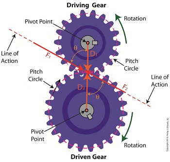
Last time we examined how torque and force are created upon the driving gear within a simple gear train. Today we’ll see how they affect the driven gear. Looking at the gear train illustration above, we see that each gear has both distance and force vectors. We’ll call the driving gear Distance vector, D1, and the driven gear Distance vector, D2. Each of these Distance vectors extend from pivot points located at the centers of their respective gear shafts. From there they extend in opposite directions until they meet at the line of action, the imaginary line which represents the geometric path along which Force vectors F1 and F2 are aligned. As we learned last time, the Force vector, F1, results from the torque that’s created at the pivot point located at the center of the driving gear. This driving gear is mounted on a shaft that’s attached to an electric motor, the ultimate powering source behind the torque. F1 follows a path along the line of action until it meets with the driven gear teeth, where it then exerts its pushing force upon them. It’s met by Force vector F2, a resisting force, which extends along the same line of action, but in a direction opposite to that of F1. These two Force vectors butt heads, pushing back against one another. F2 is essentially a negative force manifested by the dead weight of the mechanical load of the machinery components resting upon the shaft of the driving gear. Its unmoving inertia resists being put into motion. In order for the gears in the gear train to turn, F1 must be greater than F2, in other words, it must be great enough to overcome the resistance presented by F2. With the two Force vectors pushing against each other along the line of action, the angle ϴ between vectors F2 and D2, is the same as the angle ϴ between F1 and D1. Next time we’ll use the angular relationship between these four vectors to develop torque calculations for both gears in the gear train. _______________________________________ |


