|
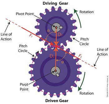
Last time we examined how torque and force are created upon the driving gear within a simple gear train. Today we’ll see how they affect the driven gear. Looking at the gear train illustration above, we see that each gear has both distance and force vectors. We’ll call the driving gear Distance vector, D1, and the driven gear Distance vector, D2. Each of these Distance vectors extend from pivot points located at the centers of their respective gear shafts. From there they extend in opposite directions until they meet at the line of action, the imaginary line which represents the geometric path along which Force vectors F1 and F2 are aligned. As we learned last time, the Force vector, F1, results from the torque that’s created at the pivot point located at the center of the driving gear. This driving gear is mounted on a shaft that’s attached to an electric motor, the ultimate powering source behind the torque. F1 follows a path along the line of action until it meets with the driven gear teeth, where it then exerts its pushing force upon them. It’s met by Force vector F2, a resisting force, which extends along the same line of action, but in a direction opposite to that of F1. These two Force vectors butt heads, pushing back against one another. F2 is essentially a negative force manifested by the dead weight of the mechanical load of the machinery components resting upon the shaft of the driving gear. Its unmoving inertia resists being put into motion. In order for the gears in the gear train to turn, F1 must be greater than F2, in other words, it must be great enough to overcome the resistance presented by F2. With the two Force vectors pushing against each other along the line of action, the angle ϴ between vectors F2 and D2, is the same as the angle ϴ between F1 and D1. Next time we’ll use the angular relationship between these four vectors to develop torque calculations for both gears in the gear train. _______________________________________ |
Posts Tagged ‘pivot point’
Distance and Force Vectors of a Simple Gear Train
Monday, May 5th, 2014Torque and Force
Tuesday, April 29th, 2014|
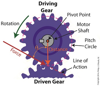
We’ve been discussing torque and how it enables more power to be available to applications such as loosening tight nuts with a wrench. Now we’ll see how those same principles apply to another application, a simple gear train. To review, the torque formula is, Torque = Distance × Force × sin(ϴ) where, Distance and Force are vector magnitudes and ϴ is the angle formed between them. Referring to the gear train illustration above, we see that Force and Distance vectors are present, just as they had been in our previous wrench/nut example. But instead of torque being created by way of force that’s applied to a wrench, things are reversed, and it’s the torque that creates the force. You see, in the wrench/nut example, the force applied to the wrench handle created torque on the nut. In our present gear train example, the torque applied to the motor shaft is created by an electric motor exerting pressure upon the motor shaft, which in turn exerts a force upon the driving gear teeth. The driving gear is also attached to this shaft, so torque causes the driving gear to rotate along with the motor. This rotation results in a force being exerted at the point where the teeth of the driving gear mesh with the teeth of the driven gear. In other words, in the wrench/nut example force created torque, while in the present example torque creates a force. The gear train has a pivot point, as there was in our wrench/nut example, but this time it’s located at the center of the motor shaft rather than at the center of a nut. The pivot point in both examples is where the action takes place. The motor’s shaft and driving gear rotate around it, just as the wrench jaws and handle rotated around the nut’s pivot point. In both examples, the Distance vectors extend out from the pivot points to meet up with the Force vector’s path. In the gear train example, this Force vector path is called a line of action, as introduced earlier in this blog series. This line of action passes through to the point where the driving and driven gear teeth mesh. The force acting upon that point causes the gears in the gear train to rotate, and as they turn mechanical energy is transferred from the motor to whatever machinery component is attached to the shaft of the driven gear. The powered component will then be able to perform useful work such as cutting lumber, mixing frosting for a cake, drilling holes in steel, or propelling vehicles. You will note that there is an angle ϴ which exists between the Distance and Force vectors. Since we have a pivot point, a Force vector, a Distance vector, and an angle ϴ, we are able to apply the torque formula to gear trains exactly as we did in our wrench/nut example. We can then use that formula to calculate how torque is transmitted between gears in the train. Next time we’ll examine the distance and force vectors in a simple gear train. _______________________________________ |
Achieving Mechanical Advantage Through Torque
Wednesday, March 19th, 2014|
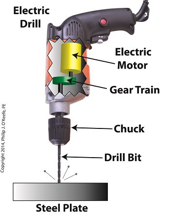
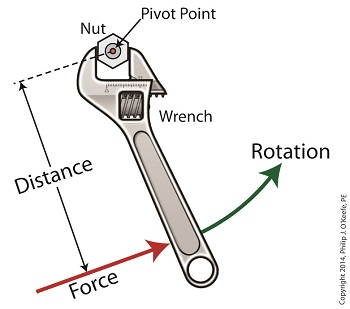
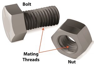
Last time we saw how gear train ratios allow us to change the speed of the driven gear relative to the driving gear. Today we’ll extend this concept further and see how gear trains are used to amplify the mechanical power output of small motors and in so doing create a mechanical advantage, an advantage made possible through the physics of torque. Below is an ordinary electric drill. Let’s see what’s inside its shell. There’s a whole lot of mechanical advantage at work here, giving the drill’s small motor the ability to perform big jobs. A motor and gear train are housed within the drill itself. The motor shaft is coupled to the chuck shaft via the gear train, and by extension, the drill bit. A chuck holds the drill bit in place. It’s the drill’s gear train that provides the small motor with the mechanical advantage necessary for this hand-held power tool to perform the big job of cutting through a thick steel plate. If the gear train and its properly engineered gear ratio weren’t in place and the chuck’s shaft was connected directly to the motor shaft, the motor would be overwhelmed and would stall or become damaged. Either way, the work won’t get done. To understand how operations like these can be performed, we must first familiarize ourselves with the physics concept of torque. Torque allows us to analyze the rotational forces acting upon rotating objects, such as gears in a gear train and wrenches on nuts and bolts. Manipulating torque allows us to achieve a physical advantage when rotating objects around a pivot point. Let’s illustrate this by using a wrench to turn a nut. The nut is fastened to the bolt with threads, interconnecting spiral grooves formed on both the inside of the nut and the outside of the bolt. A wrench is used to loosen and tighten the nut by rotating it on its mating threads. The nut itself rotates about a pivot point which lies at its center. When you use your arm to manipulate the wrench you apply force, a force which is transmitted at a distance from the pivot point. This in turn creates a torque on the nut. In other words, torque is a function of the force acting upon the handle relative to its distance from the pivot point at the center of the nut. Torque can be increased by changing one or both of its acting factors, force and distance. We’ll see how next time when we examine the formula for torque and manipulate it so that a weak arm can loosen even the tightest nut. _______________________________________ |
