|
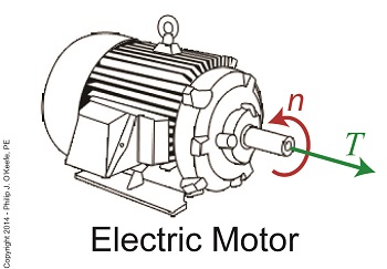
Last time we learned that we can get more torque out of a motor by using one of two methods. In the first method we attach a gear train to the motor, then try different gear sizes until we arrive at the desired torque for the application. In the second method we eliminate the gear train altogether and simply use a higher horsepower motor to give us the torque we need. Today we’ll explore the second method. We’ll use the equation presented in our last blog to determine torque, T, relative to a motor’s horsepower, HP, when the motor operates at a speed, n: T = [HP ÷ n] × 63,025 In earlier blogs in this series we employed a gear train attached to an electric motor to power a lathe. It provided an insufficient 200 inch pounds of torque when 275 is required. Let’s use the equation and a little algebra to see how much horsepower this motor develops if it turns at a speed of 1750 RPM, a common speed for alternating current (AC) motors: 200 inch pounds = [HP ÷ 1750 RPM] × 63,025 200 = HP × 36.01 HP = 200 ÷ 36.01 = 5.55 horsepower For the purpose of our example today, let’s say we’ve nonsensically decided not to use a gear train, leaving us with no choice but to replace the underpowered motor with a more powerful one. So let’s see what size motor we’ll need to provide us with the required horsepower of 275 inch pounds. Using the torque equation and plugging in numbers already provided our equation becomes: 275 inch pounds = [HP ÷1750 RPM] × 63,025 275 = HP × 36.01 HP = 275 ÷ 36.01 = 7.64 horsepower This tells us that we need to replace the 5.55 horsepower motor with a 7.65 horsepower motor. As you might have guessed, the higher the motor’s horsepower, the larger that motor’s size and weight — if you’re not using a gear train, that is. Bigger, bulkier motors cost more to purchase and operate and also take up more space, which often makes them impractical to use. All this translates to the reality that sometimes it just makes more sense to use a gear train to provide more torque. It’s a lot easier and cheaper to attach a gear train to a motor and manipulate its gear sizes to arrive at desired torque than it is to buy a bigger motor. You may have deduced by now that it’s relatively easy to get more torque. Almost too easy. Next time we’ll see how increased torque comes at another type of cost, the cost of speed. _______________________________________
|
Posts Tagged ‘motor’
Equations Used to Manipulate Torque Relative to Horsepower
Monday, July 28th, 2014
Determining Torque Within a Gear Train
Monday, June 30th, 2014|
Last time we set up an example where an electric motor is connected to a lathe via a gear train. Today we’ll take the numerical values present on that gear train and plug them into the torque ratio equation we’ve been working with for the past few blogs. In the illustration below the electric motor exerts 200 inch pounds of torque upon the driving gear. The driving gear pitch circle diameter is 6 inches, while the driven gear pitch circle diameter is 8 inches. It’s been determined through previous lab testing that the lathe we’ll be using requires at least 275 inch pounds of torque to be exerted upon the driven gear shaft in order to operate properly. Will the gear train shown below meet this requirement?
First, a review of the torque ratio equation: T1 ÷ T2 = D1 ÷ D2 Now we’ll crunch numbers. T1 is equal to 200 inch pounds, D1 is equal to 3 inches (pitch radius equals pitch diameter divided by two), and D2 is equal to 4 inches. This gives us: (200 inch pounds) ÷ T2 = (3 inches) ÷ (4 inches) T2 = (200 inch pounds) ÷ (0.75) = 266.67 inch pounds So, does the gear train as presented here supply enough torque to power the lathe properly? No, it does not. It provides only 266.67 inch pounds, not the 275 inch pounds of torque required. Next time we’ll see how to manipulate gear sizes within a gear train in order to meet a given torque requirement. _______________________________________
|

Gear Trains Are Torque Converters and Why That’s Important
Friday, June 13th, 2014|
Today we’ll analyze the relationship between the sizes of the gears within a gear train, as well as their torques, and get an understanding of how gear trains act as torque converters. Last time we developed a single torque equation for a simple gear train: T1 ÷ D1 = T2 ÷ D2 (1) where T1 and T2 are the driving and driven gear torques, and D1 and D2 are the driving and driven gear pitch circle radii. The first thing to be done in order to arrive at a torque conversion analysis is group together like terms in equation (1) so that we end up with terms relating to torque on one side of the equation and terms relating to gear size on the other. We’ll use algebra to divide both sides of the equation by T2 , then multiply both sides by D1. After doing so we get, T1 ÷ T2 = D1 ÷ D2 (2) In equation (2), T1 ÷ T2 is a torque ratio. Ratio means we’re dividing one of the torques by the other. Likewise, D1 ÷ D2 is a gear pitch radius ratio, that is to say, it’s the ratio of one gear’s physical size relative to the physical size of the other. What equation (2) tells us is that the individual gears on the gear train will produce torque values which are dependent upon the physical sizes of the two gears with respect to one another.
So what’s the practical significance of this? When gear trains are used in industrial applications, they always act as torque converters. One such example would be when a low-torque-producing electric motor is used to power a steel cutting lathe. If the motor isn’t tough enough to power the lathe, it itself won’t be modified, but the torque it produces will be. This modification is accomplished by converting the motor’s low torque value, T1, to a higher torque value, T2 , and it’s equation (2) that’s used to do it. Next time we’ll delve deeper into the methodology behind gear train torque conversions. _______________________________________
|

Achieving Mechanical Advantage Through Torque
Wednesday, March 19th, 2014|
Last time we saw how gear train ratios allow us to change the speed of the driven gear relative to the driving gear. Today we’ll extend this concept further and see how gear trains are used to amplify the mechanical power output of small motors and in so doing create a mechanical advantage, an advantage made possible through the physics of torque. Below is an ordinary electric drill. Let’s see what’s inside its shell.
There’s a whole lot of mechanical advantage at work here, giving the drill’s small motor the ability to perform big jobs. A motor and gear train are housed within the drill itself. The motor shaft is coupled to the chuck shaft via the gear train, and by extension, the drill bit. A chuck holds the drill bit in place. It’s the drill’s gear train that provides the small motor with the mechanical advantage necessary for this hand-held power tool to perform the big job of cutting through a thick steel plate. If the gear train and its properly engineered gear ratio weren’t in place and the chuck’s shaft was connected directly to the motor shaft, the motor would be overwhelmed and would stall or become damaged. Either way, the work won’t get done. To understand how operations like these can be performed, we must first familiarize ourselves with the physics concept of torque. Torque allows us to analyze the rotational forces acting upon rotating objects, such as gears in a gear train and wrenches on nuts and bolts. Manipulating torque allows us to achieve a physical advantage when rotating objects around a pivot point. Let’s illustrate this by using a wrench to turn a nut.
The nut is fastened to the bolt with threads, interconnecting spiral grooves formed on both the inside of the nut and the outside of the bolt. A wrench is used to loosen and tighten the nut by rotating it on its mating threads. The nut itself rotates about a pivot point which lies at its center.
When you use your arm to manipulate the wrench you apply force, a force which is transmitted at a distance from the pivot point. This in turn creates a torque on the nut. In other words, torque is a function of the force acting upon the handle relative to its distance from the pivot point at the center of the nut. Torque can be increased by changing one or both of its acting factors, force and distance. We’ll see how next time when we examine the formula for torque and manipulate it so that a weak arm can loosen even the tightest nut. _______________________________________ |


Gear Reduction
Wednesday, March 5th, 2014|
Last time we learned there are two formulas used to calculate gear ratio, R. Today we’ll see how to use them to calculate a gear reduction between gears in a gear train, a strategy which enables us to reduce the speed of the driven gear in relation to the driving gear. If you’ll recall from last time, our formulas to determine gear ratio are: R = NDriven ÷ NDriving (1) R = nDriving ÷ nDriven (2) Now let’s apply them to this example gear train to see how a gear reduction works.
Here we have a driven gear with 23 teeth, while the driving gear has 18. For our example the electric motor connected to the driving gear causes it to turn at a speed, nDriving, of 3600 revolutions per minute (RPM). Knowing these numerical values we are able to determine the driven gear speed, nDriven. First we’ll use Formula (1) to calculate the gear ratio using the number of teeth each gear has relative to the other: R = NDriven ÷ NDriving R = 23 Teeth ÷ 18 Teeth R = 1.27 In gear design nomenclature, the gear train is said to have a 1.27 to 1 ratio, commonly denoted as 1.27:1. This means that for every tooth on the driving gear, there are 1.27 teeth on the driven gear. Interestingly, the R’s in both equations (1) and (2) are identical, and in our situation is equal to 1.27, although it is arrived at by different means. In Formula (1) R is derived from calculations involving the number of teeth present on each gear, while Formula (2)’s R is derived by knowing the rotational speeds of the gears. Since R is the common link between the two formulas, we can use this commonality to create a link between them and insert the R value determined in one formula into the other. Since we have already determined that the R value is 1.27 using Formula (1), we can replace the R in Formula (2) with this numerical value. As an equation this looks like: R = 1.27 = nDriving ÷ nDriven Now all we need is one more numerical value to solve Formula (2)’s equation. We know that the speed at which the driving gear is rotating, nDriving , is 3600 RPM. We use basic algebra to calculate the driven gear speed, nDriven : 1.27 = 3600 RPM ÷ nDriven nDriven = 3600 RPM ÷ 1.27 = 2834.65 RPM Based on our calculations, the driven gear is turning at a speed that is slower than the driving gear. To determine exactly how much slower we’ll calculate the difference between their speeds: nDriving – nDriven = 3600 RPM – 2834.65 RPM ≈ 765 RPM So in this gear reduction the driven gear turns approximately 765 RPM slower than the driving gear. Next time we’ll apply a gear reduction to a gear train and see how to arrive at a particular desired output speed. _______________________________________ |

Gear Terminology
Sunday, January 5th, 2014|
Last time we reviewed the ancient origins of gears and saw how they’ve been around a lot longer than most people realize. Now let’s familiarize ourselves with the terminology of modern gears by taking a look at the most basic and commonly used gear construction, the spur gear. A spur gear is shown below, so named due to its resemblance to spurs commonly found attached to horse riding boots.  Spur Gear At their most basic gears are wheels containing many projections which resemble teeth. These teeth are equally spaced around the wheel’s circumference and are designed to mesh, or fit together, with the teeth of other like gears. Looking more closely at the teeth of a modern spur gear, we see they have a rather complex and peculiar curved shape, along with their own terminology.  Gear Tooth Terminology There’s a pitch circle that intersects each gear tooth between the root of the tooth, or bottom land, and the tip of the tooth, or top land. Above the pitch circle each tooth side bears a face. Below the pitch circle and under each face is a flank. Spur gear teeth don’t necessarily have to have this shape. All that’s required is that the teeth fit together in such a way so as to permit fluid interaction between them as they rotate. As a matter of fact, some primitive gears consisted of wooden wheels with teeth made of wooden pegs. These pegs were inserted into evenly spaced holes which were drilled around the circumference of the wheel. The wooden pegs of each wheel would mesh with one another, and when one gear wheel was caused to rotate, its pegs would press against the pegs of the other gear, making it rotate along with it. So if simple pegs worked well enough, then why are modern gear teeth so specifically shaped? We’ll see why next time when we join gears together to form a gear train. ________________________________________ |
The History of Gears
Monday, December 23rd, 2013|
Could it be that after cave men invented the wheel they moved on to invent another circular object, the gear? Gear assemblies are found in a wide variety of applications, from tiny ones used inside wrist watches to massive ones found in aircraft carriers. No one knows for certain when gear technology was first employed, but we do know that gear driven machinery has been around since before the Industrial Revolution. As far back as the Renaissance we’ve documented their use within flour milling equipment and the first primitive clocks. Going even further back in time, Roman engineers are known to have developed a primitive gear driven odometer. It was attached to horse drawn cart wheels and the number of revolutions performed allowed the distance traveled to be calculated. In fact gears have been used far longer than scientists originally thought. In October of the year 1900 sponge divers stumbled upon an ancient Roman shipwreck at the bottom of the Aegean Sea near the Greek island of Antikythera. Inside this wreck they found mineral encrusted fragments of an artifact composed of a bronze alloy. This amazing discovery appeared to be a remarkably modern looking gear assembly which would come to be known as the Antikythera Mechanism.
 The Antikythera Mechanism Analysis of the Mechanism conducted over the last 100 years has revealed it to be a highly complex device. Still visible engraved inscriptions disclose it to be of Greek origin, dating back to about 100 BC. As such it’s the oldest known complex gear driven mechanism in the world. Prior to its discovery it was thought that mechanisms of its kind were not made until 1400 AD. As to the purpose it served, that remains a subject of controversy, since many of its parts are missing.
 X-Ray View of the Antikythera Mechanism The X-ray image reveals some of the Mechanism’s hidden complexity. Based on detailed examination of these images coupled with engineering analysis, it’s theorized by scientists that the mechanism may have been configured as illustrated below.
 Possible Configuration of the Antikythera Mechanism Since there’s no evidence that ancient Greeks possessed motors, such as those used in modern clocks, some scientists believe that the gears in the Mechanism were set into motion by simply turning a hand crank. Others believe that the arrangement and size of the gears indicate that the Mechanism’s movement is analogous to planetary motion within our solar system. They theorize further that it may have been used to calculate the positions of the Sun, Moon, and other celestial bodies. Next time we’ll fast forward to present day to familiarize ourselves with the basic terminology of gears and then later see how they’re used in modern devices.
________________________________________ |
Transistors – Digital Control Interface, Part III
Sunday, July 1st, 2012| When I was in engineering school in the mid 1970s microprocessor chips were still a fairly new concept. Scientific calculators were the size of a brick back then, and they weighed almost as much, and there were no personal computers.
I remember doing homework on the UNIVAC 1108 mainframe computer at school. To program it I had to sit at a monster of a keypunching machine for which I punched an endless array of holes into paper cards. These holes acted as the programming logic to instruct the computer what functions to perform. The 1108 computer’s mainframe was so huge it was housed in an adjoining room the size of a house. Since the 1980s advances in microprocessor technology have increased computing power and dramatically reduced the size of components, making things like laptops, smart phones, and sophisticated electronic products possible. Last time we began looking at my design solution for the control of a machine which developed medical x-ray film and made use of a microprocessor chip to automate its operation. A field effect transistor (FET) acts as a digital control interface between its 5 volt direct current (VDC) microprocessor and a 12 VDC buzzer. Figure 1 shows what happens when someone presses the button to put everything into action and the microprocessor starts timing. Figure 1
With the button depressed the chip senses 5 VDC from the power supply on its input lead. This in turn signals the computer program to turn the product on. The program then begins counting down the minutes, all the while maintaining a 0 voltage output from the chip’s output lead. With no voltage present on its G lead, the FET does not permit electrical current to flow from the 12 VDC supply, through the buzzer, through D and S, and down to electrical ground. The buzzer remains silent.
Figure 2Figure 2 shows what happens when the program begins its 40-minute warming sequence. The chip raises the output lead voltage to 5 VDC and applies it to G, then the FET permits electric current to flow through it to ground from the 12 VDC supply and the buzzer. Now supplied with power, the buzzer sounds. Then, per programming instructions, after 2 seconds the program shuts off the voltage in the chip’s output lead, current is cut off, and the buzzer goes silent. Next time we’ll see how an FET can be used as an interface between a microprocessor and another higher powered device, that of a 120 VAC motor that’s used to move x-ray film through a series of processes within the developer.
____________________________________________ |


Industrial Control Basics – Manual Control
Monday, December 12th, 2011| You’ve probably heard the saying, “asleep at the switch.” It’s usually associated with some sort of disaster, found later to have been caused by human error. Someone wasn’t paying attention, and something very bad happened. The meltdown of the Soviet nuclear power plant Chernobyl in 1986 comes to mind. You may be surprised to learn that the saying has its origins in the world of industrial controls, or more specifically, manual controls, as we’ll see in this article.
Last week when we opened our discussion on manual controls, we talked about how they work just as their name implies, that is, someone must manually press a button or throw a switch in order to initiate a factory operation. In other words, a manual control requires human intervention to initiate an action, such as pushing the start button. The machine will then continue to run until a person hits the stop button. Let’s go now on a virtual field trip into a telephone factory to see how a basic manual control system works. It has a conveyor belt operated by an electric motor, and this motor is connected by wires and a power switch to a 120 volt power source of alternating current. Figure 1 illustrates what we mean. It shows that when the power switch is in the open position, a physical air gap exists within the electrical circuit. This prevents electricity from flowing through the wire because electricity can’t jump over gaps.
Figure 1 – Open Power Switch Enter a human into the scenario, someone who grabs the power switch handle and manually closes it, eliminating the air gap. See Figure 2.
Figure 2 – Closed Power Switch When the power switch is closed, a metal conductor bridges the gap, causing electricity to flow through the metal conductor to the electric motor in the circuit. This brings life to the conveyor belt. As long as the power switch remains closed, the conveyor belt will continue to operate. That’s it, that’s a basic manual control system. It’s simple to operate, but it does have one major flaw. It requires constant monitoring by a human. Aside from opening and closing a power switch, humans are required to monitor operations, in case something goes wrong. The operator watching over an industrial machine performs the same function as the pilot on a plane, that is, to start-stop operations, and to intervene in case of an emergency. Computers fly modern jets. Pilots serve as trouble shooters when the unanticipated disaster situation occurs, because computers can’t yet creatively problem solve. Next time we’ll introduce the element of an automatic control system, which will virtually eliminate the need for human intervention and with it human error. ____________________________________________ |


