|
We’ve been working towards a general understanding of how gear trains work, and today we’ll solve a final piece of the puzzle when we identify how increased gear train torque is gained at the expense of gear train speed. Last time we developed a mathematical relationship between the torque, T, and the rotational speed, n, of the driving and driven gears in a simple gear train. This is represented by equation (8): TDriven ÷ TDriving = nDriving ÷ nDriven (8) For the purpose of our example we’ll assume that the driving gear is mounted to an electric motor shaft spinning at 100 revolutions per minute (RPM) and which produces 50 inch pounds of torque. Previous lab testing has determined that we require a torque of 100 inch pounds to properly run a piece of machinery that’s powered by the motor, and we’ve decided that the best way to get the required torque is not to employ a bigger, more powerful motor, but rather to install a gear train and manipulate its gear sizes until the desired torque is obtained. We know that using this approach will most likely affect the speed of our operation, and we want to determine how much speed will be compromised. So if the torque on the driven gear needs to be 100 inch pounds, then what will be the corresponding speed of the driven gear? To answer this question we’ll insert the numerical information we’ve been provided into equation (8). Doing so we arrive at the following: TDriven ÷ TDriving = nDriving ÷ nDriven (100 inch pounds) ÷ (50 inch pounds) = (100 RPM) ÷ nDriven 2 = (100 RPM) ÷ nDriven nDriven = (100 RPM) ÷ 2 = 50 RPM This tells us that in order to meet our torque requirement of 100 inch pounds, the gear train motor’s speed must be reduced from 100 RPM to 50 RPM, which represents a 50% reduction in speed, hence the tradeoff.
This wraps up our blog series on gears and gear trains. Next time we’ll move on to a new topic: Galileo’s experiments with falling objects.
_______________________________________
|
Posts Tagged ‘gear expert’
Determining the Gear Train Tradeoff of Torque vs. Speed, Part Three
Wednesday, August 27th, 2014
Determining the Gear Train Tradeoff of Torque vs. Speed, Part One
Friday, August 15th, 2014|
Hold onto your hats, we’re going to deal with a lot of equations today! Last time we used flashbacks to previous blogs in this series to revisit key equations in our ongoing discussion of gear trains and torque. We also introduced The Law of Conservation of Energy in conjunction with five equations that together demonstrate how when increasing torque by use of a simple gear train, we do so at the cost of speed. Those five equations are:
where, R is the gear ratio, N the number of gear teeth, n the gear’s rotational speed, T the torque, D the gear pitch radius, and HP is the horsepower transmitted by the gears.
As we work the equations, keep in mind that our ultimate objective is to find a way to link together (1) and (2), the equations dealing with gear torque and speed. Once we accomplish this we’ll see how increased torque is obtained at the cost of speed. But because there are no common terms between equations (1) and (2), our first step is to develop one. Developing a link between equations (1) and (2) is a process that begins with combining equations (2), (3), and (4).
The common terms in these three equations are TDriving and TDriven, so we’ll manipulate things in order to group them together. We’ll substitute equation (3) for the TDriving term in equation (2), and substitute equation (4) for the TDriven term in equation (2). We are now able to link all three equations to get: {[HPDriving ÷ nDriving] × 63,025} ÷ {[HPDriven ÷ nDriven] × 63,025} = DDriving ÷ DDriven (6) Now let’s go a step further to simplify equation (6). From equation (5) we know that the driving and driven gear horsepowers are equal. So, in equation (6), the HPDriving and HPDriven cancel out, along with the two 63,025 terms, allowing us to arrive at equation (7): {[HPDriving ÷ nDriving] × 63,025} ÷ {[HPDriven ÷ nDriven] × 63,025} = DDriving ÷ DDriven
Next week we’ll use equation (7) to link together R, N, n, of equation (1) with D and T of equation (2) and in so doing disclose mathematically the tradeoff between torque and speed, then apply our findings to an example. _______________________________________
|

The Methodology Behind Gear Train Torque Conversions
Sunday, June 22nd, 2014|
Last time we learned that gear trains are torque converters, and we developed a torque ratio equation which mathematically ties the two gears in a gear train together. That equation is: T1 ÷ T2 = D1 ÷ D2 Engineers typically use this equation knowing only the value for T2, the torque required to properly drive a piece of machinery. That knowledge is acquired through trial testing during the developmental phase of manufacturing. Once T2 is known, a stock motor is selected from a catalog with a torque value T1 which closely approximates that of the required torque, T2. Then calculations are performed and lab tests are run to determine the driving and driven gear sizes, D1 and D2 which will enable the gear train to convert T1 into the required value of T2. This series of operations are often a time consuming and complex process. To simplify things for the purpose of our example, we’ll say we’ve been provided with all values required for our equation, except one, the value of T2. In other words, we’ll be doing things in a somewhat reverse order, because our objective is simply to see how a gear train converts a known torque T1 into a higher torque T2.
We’ll begin by considering the gear train illustration above. For our purposes it’s situated between an electric motor and the lathe it’s powering. The motor exerts a torque of 200 inch pounds upon the driving gear shaft of the lathe, a torque value that’s typical for a mid sized motor of about 5 horsepower. As-is, this motor is unable to properly drive the lathe, which is being used to cut steel bars. We know this because lab testing has shown that the lathe requires at least 275 inch pounds of torque in order to operate properly. Will the gears on our gear train be able to provide the required torque? We’ll find out next time when we insert values into our equation and run calculations. _______________________________________
|

Gear Train Torque Equations
Thursday, May 22nd, 2014|
In our last blog we mathematically linked the driving and driven gear Force vectors to arrive at a single common vector F, known as the resultant Force vector. This simplification allows us to achieve common ground between F and the two Distance vectors of our driving and driven gears, represented as D1 and D2. We can then use this commonality to develop individual torque equations for both gears in the train.
In this illustration we clearly see that the Force vector, F, is at a 90º angle to the two Distance vectors, D1 and D2. Let’s see why this angular relationship between them is crucial to the development of torque calculations. First a review of the basic torque formula, presented in a previous blog, Torque = Distance × Force × sin(ϴ) By inserting D1, F, and ϴ = 90º into this formula we arrive at the torque calculation, T1 , for the driving gear in our gear train: T1 = D1 × F × sin(90º) From a previous blog in this series we know that sin(90º) = 1, so it becomes, T1 = D1 × F By inserting D2, F, and ϴ = 90º into the torque formula, we arrive at the torque calculation, T2 , for the driven gear: T2 = D2 × F × sin(90º) T2 = D2 × F × 1 T2 = D2 × F Next week we’ll combine these two equations relative to F, the common link between them, and obtain a single equation equating the torques and pitch circle radii of the driving and driven gears in the gear train. _______________________________________ |

The Mathematical Link Between Gears in a Gear Train
Wednesday, May 14th, 2014|
Last time we analyzed the angular relationship between the Force and Distance vectors in this simple gear train. Today we’ll discover a commonality between the two gears in this train which will later enable us to develop individual torque calculations for them.
From the illustration it’s clear that the driving gear is mechanically linked to the driven gear by their teeth. Because they’re linked, force, and hence torque, is transmitted by way of the driving gear to the driven gear. Knowing this we can develop a mathematical equation to link the driving gear Force vector F1 to the driven gear Force vector F2, then use that linking equation to develop a separate torque formula for each of the gears in the train. We learned in the previous blog in this series that F1 and F2 travel in opposite directions to each other along the same line of action. As such, both of these Force vectors are situated in the same way so that they are each at an angle value ϴ with respect to their Distance vectors D1 and D2. This fact allows us to build an equation with like terms, and that in turn allows us to use trigonometry to link the two force vectors into a single equation: F = [F1 × sin(ϴ)] – [F2 × sin(ϴ)] where F is called a resultant Force vector, so named because it represents the force that results when the dead, or inert, weight that’s present in the resisting force F2 cancels out some of the positive force of F1. Next week we’ll simplify our gear train illustration and delve into more math in order to develop separate torque computations for each gear in the train. _______________________________________ |

Gear Reduction
Wednesday, March 5th, 2014|
Last time we learned there are two formulas used to calculate gear ratio, R. Today we’ll see how to use them to calculate a gear reduction between gears in a gear train, a strategy which enables us to reduce the speed of the driven gear in relation to the driving gear. If you’ll recall from last time, our formulas to determine gear ratio are: R = NDriven ÷ NDriving (1) R = nDriving ÷ nDriven (2) Now let’s apply them to this example gear train to see how a gear reduction works.
Here we have a driven gear with 23 teeth, while the driving gear has 18. For our example the electric motor connected to the driving gear causes it to turn at a speed, nDriving, of 3600 revolutions per minute (RPM). Knowing these numerical values we are able to determine the driven gear speed, nDriven. First we’ll use Formula (1) to calculate the gear ratio using the number of teeth each gear has relative to the other: R = NDriven ÷ NDriving R = 23 Teeth ÷ 18 Teeth R = 1.27 In gear design nomenclature, the gear train is said to have a 1.27 to 1 ratio, commonly denoted as 1.27:1. This means that for every tooth on the driving gear, there are 1.27 teeth on the driven gear. Interestingly, the R’s in both equations (1) and (2) are identical, and in our situation is equal to 1.27, although it is arrived at by different means. In Formula (1) R is derived from calculations involving the number of teeth present on each gear, while Formula (2)’s R is derived by knowing the rotational speeds of the gears. Since R is the common link between the two formulas, we can use this commonality to create a link between them and insert the R value determined in one formula into the other. Since we have already determined that the R value is 1.27 using Formula (1), we can replace the R in Formula (2) with this numerical value. As an equation this looks like: R = 1.27 = nDriving ÷ nDriven Now all we need is one more numerical value to solve Formula (2)’s equation. We know that the speed at which the driving gear is rotating, nDriving , is 3600 RPM. We use basic algebra to calculate the driven gear speed, nDriven : 1.27 = 3600 RPM ÷ nDriven nDriven = 3600 RPM ÷ 1.27 = 2834.65 RPM Based on our calculations, the driven gear is turning at a speed that is slower than the driving gear. To determine exactly how much slower we’ll calculate the difference between their speeds: nDriving – nDriven = 3600 RPM – 2834.65 RPM ≈ 765 RPM So in this gear reduction the driven gear turns approximately 765 RPM slower than the driving gear. Next time we’ll apply a gear reduction to a gear train and see how to arrive at a particular desired output speed. _______________________________________ |

Spur Gears In Motion
Wednesday, February 12th, 2014|
Last time we learned about forces generated when spur gear teeth mesh and move along a specific line of action. Today we’ll see them in movement. Looking at the illustration below it might appear that there are three teeth in contact, but this isn’t the case. As the gears rotate, only two teeth make contact at any given time, although the third tooth comes very close. The actual point of contact between the teeth is represented by a black dot on the illustration below. This is where two opposing forces, F1 and F2, meet.
Now let’s animate the illustration to see how the line of action remains constant the entire time the gear teeth are in motion. By constant I mean that this imaginary line’s position and angle does not change relative to the gears throughout the course of their movement.
In the animation, the point of contact moves along the line of action as the gears turn. Each tooth’s involute profile ensures that smooth contact is maintained along the faces and flanks of the gear teeth. The involute profile’s unique shape facilitates opposing teeth remaining in constant contact along the line of action for the duration of their movement together. If the gear tooth profile wasn’t involute in its shape, say for example it was square or triangular, the forces acting upon the meshed teeth during movement would vary in direction and intensity as a result of uneven contact between the teeth. For example, consider the square shaped tooth profile in the gear train below.
As the gears rotate, the pointed tip of one tooth strikes the flat face of another. As they continue to turn, the two flat faces of the teeth slap together, then the pointed tip of one tooth will strike the flat face of the other tooth, and so forth. The result is movement that is jerky and destructive. There would be excessive vibration and wear and tear on the teeth, resulting in rapid gear tooth erosion and decreased efficiency overall. Next time we’ll introduce the gear ratio, a formula which allows us to alter the rotational speed of the driven gear in relation to that of the driving gear, something which comes in handy when designing things that require this differential.
_______________________________________ |


Overcoming Inertia
Monday, February 3rd, 2014|
Inertia. It’s the force that keeps us in bed after the alarm has rung. It seems to have a life of its own, and today we’ll see how it comes into play in keeping other stationary objects at rest. Last time we identified a specific point of contact between spur gear teeth in a gear train and introduced the opposing forces, F1 and F 2, generated there. Today we’ll see what these forces represent, identifying one of them as inertia.
So where do these forces come from? They’re forces generated by different means that converge at the same point of contact, the point at which gear teeth mesh. They follow a very specific geometric path to meet there, an imaginary straight line referred to as the line of action. F1 is always generated by a source of mechanical energy. In our locomotive example introduced earlier in this blog series that source is an electric traction motor, upon which a driving gear is mounted. When the motor is energized, a driving force F1 is generated, which causes gear teeth on the driving gear to push against gear teeth of the driven gear. Force F2 is not as straightforward to understand, because it’s not generated by a motor. Instead, it’s the resisting force that the weight of a stationary object poses against its being moved from an at-rest position, known as inertia. The heavier the object, the more inertia it presents with. Trains, of course, are extremely heavy, and to get them to move a great deal of inertia must be overcome. Inertia is also a factor in attempting to stop objects already in motion. To get a stationary locomotive to move, mechanical energy must be transmitted from the driving gear that’s attached to its traction motor, then on to the driven gear attached to its axle. At their point of contact, the driving force of the motor, F1, is met by the resisting force of inertia, F2. In order for the train to move, F1 must be greater than F2. If F1 is less than or equal to F2, then the train won’t leave the station. Next week we’ll animate our static image and watch the interplay between gear teeth, taking note of the line of action during their movement.
_______________________________________ |

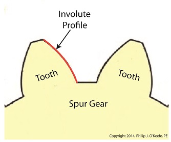
Spur Gear Tooth Geometry and the Involute Curve
Sunday, January 19th, 2014|
Last time we learned how spur gears mesh together to form a gear train and we examined a train consisting of just two gears, one being the driving gear, the other the driven gear. Today we’ll take a look at the geometry behind the smooth functioning of modern spur gear teeth when we identify their peculiar shape to be that of an involute curve. The curved profile of spur gear teeth conforms to a type of mathematical curve found in geometry known as an involute. The involute profile of a spur gear tooth is shown in red below. The mathematical notion of the involute was first presented in 1673 by Dutch mathematician Christiaan Huygens, in his book, Horologium Oscillatorium. Huygens’ book presents his studies on clock pendulums and the applied mathematics he used in an effort to predict their often erratic motion on ships at sea. His book ultimately dealt with far more than this, resulting in a treatise on the mathematical properties of the involutes of curves. To see how an involute curve is formed, we’ll conduct a simple experiment. One end of string is attached with a tack to a circular object, like the yellow rod shown in the following illustration. The other end of string has a red ball attached to it.
 Forming An Involute Curve If we grab the ball and pull the string taught while wrapping the string around the rod, the ball’s path will form an involute curve due to the incremental shortening of the string that occurs as it wraps around the rod. Next time we’ll see how the involute profile of gear teeth contributes to efficient mechanical energy transmission in gear trains. _______________________________________ |

Gear Trains
Monday, January 13th, 2014|
Last time we covered the basic terminology of spur gears. Today we’ll see how they interact with one another to form a gear train, such as the one depicted below.
 Meshing Spur Gears Form A Gear Train A gear train is formed when the teeth of two or more gears mesh and work together for the purpose of powering a mechanical device. A gear train can consist of as little as two gears, but trains can be so large as to contain dozens of gears, depending on the complexity of the device they are powering. But no matter how many gears are employed, there are certain key features that are shared by every gear train assembly. First, one gear within the train must be attached to a shaft rotated by a source of mechanical energy, such as an engine or electric motor. This gear is called the driving gear. The second requirement of a gear train is that at least one gear other than the driving gear is mounted to the shaft of a rotating machine part. This gear is called the driven gear.
 Locomotive Gear Train Consisting Of Two Gears The illustration above shows an exploded view of a locomotive gear train assembly consisting of two gears. The driving gear is mounted to the shaft of an electric traction motor. The driven gear is mounted to the locomotive’s axle. When a motor is attached to the axle, the two gears mesh together. The traction motor converts electrical energy into mechanical energy, which is supplied to the driving gear via the spinning motor’s shaft. The teeth of the driving gear then transmit the motor’s mechanical energy to the teeth of the driven gear, which then turn the locomotive’s wheels. It’s just one of countless operations that can be performed with gear train assemblies. Next time we’ll examine the geometry behind modern spur gear tooth design. _______________________________________ |


