|
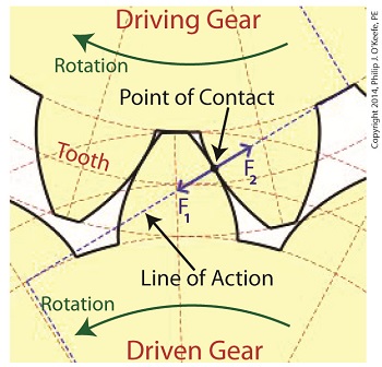
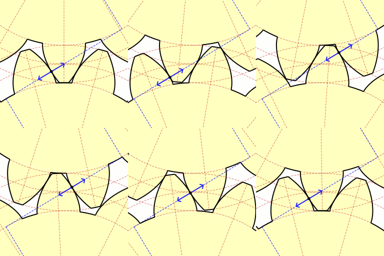
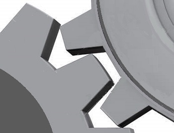
Last time we learned about forces generated when spur gear teeth mesh and move along a specific line of action. Today we’ll see them in movement. Looking at the illustration below it might appear that there are three teeth in contact, but this isn’t the case. As the gears rotate, only two teeth make contact at any given time, although the third tooth comes very close. The actual point of contact between the teeth is represented by a black dot on the illustration below. This is where two opposing forces, F1 and F2, meet. Now let’s animate the illustration to see how the line of action remains constant the entire time the gear teeth are in motion. By constant I mean that this imaginary line’s position and angle does not change relative to the gears throughout the course of their movement. In the animation, the point of contact moves along the line of action as the gears turn. Each tooth’s involute profile ensures that smooth contact is maintained along the faces and flanks of the gear teeth. The involute profile’s unique shape facilitates opposing teeth remaining in constant contact along the line of action for the duration of their movement together. If the gear tooth profile wasn’t involute in its shape, say for example it was square or triangular, the forces acting upon the meshed teeth during movement would vary in direction and intensity as a result of uneven contact between the teeth. For example, consider the square shaped tooth profile in the gear train below. As the gears rotate, the pointed tip of one tooth strikes the flat face of another. As they continue to turn, the two flat faces of the teeth slap together, then the pointed tip of one tooth will strike the flat face of the other tooth, and so forth. The result is movement that is jerky and destructive. There would be excessive vibration and wear and tear on the teeth, resulting in rapid gear tooth erosion and decreased efficiency overall. Next time we’ll introduce the gear ratio, a formula which allows us to alter the rotational speed of the driven gear in relation to that of the driving gear, something which comes in handy when designing things that require this differential.
_______________________________________ |
Posts Tagged ‘meshed gears’
Spur Gears In Motion
Wednesday, February 12th, 2014Meshed Gear Teeth and Their Point of Contact
Monday, January 27th, 2014|
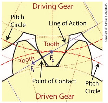
Last time we learned that the geometric shape specific to spur gear teeth is known as an involute profile. Today we’ll look at the geometry behind this profile and the very specific place at which gear teeth meet, known as the point of contact. The transmission of mechanical energy between meshed gears may seem on its face to be straightforward, after all their gears are interlaced and interact with one another. But their interaction involves some rather complex geometry, because forces are directed in a peculiar fashion between the teeth of the driving and driven gears. Let’s consider the following illustration to get a better understanding.
As we learned previously in this series, the pitch circle of a gear is an imaginary arc passing through each tooth between their top and bottom lands. The pitch circles of the driving and driven gears are represented by heavy red dashed lines in the illustration. To ensure proper alignment and smooth action between gear teeth during rotation, the gears are spaced so that their pitch circles just meet but never intersect. This specific point is known as the point of contact. It is the only point at which gears will come into actual physical contact with one another, and it provides just enough contact so that when the driving gear turns in one direction, say clockwise, its teeth exert pressure upon the driven gear teeth, forcing it to move in the opposite direction, counterclockwise. The forces which come into play at the point of contact are represented in the illustration by a black dot with oppositional blue arrows extending from it. These arrows represent the opposing mechanical forces, F1 and F2 , which act upon the teeth when they make contact. We’ll learn more about the effect of those forces next time when we follow a locomotive from a stationary position into one of movement.
_______________________________________ |


