|
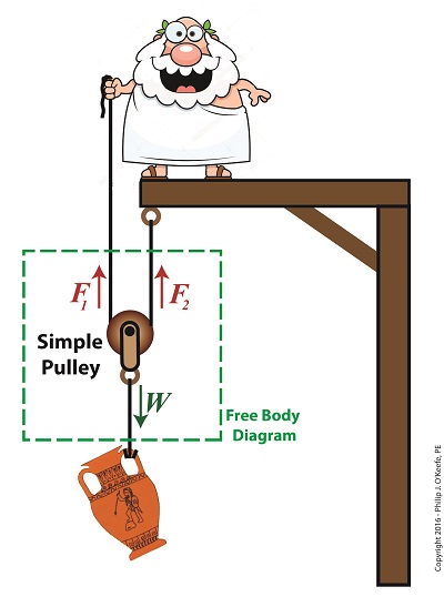
Last time we introduced the free body diagram, applied it to a simple pulley, and discovered that in so doing lifting objects required 50% less effort. As an engineering expert, I’ve sometimes put this improved version of a simple pulley to work for me in designs. We’ll do the math behind the improvement today. Here again is the free body diagram showing the improved simple pulley as introduced last week.
The Math Behind the Improved Simple Pulley
The illustration shows the three forces, F1, F2, and W, acting upon the simple pulley within the highlighted free body diagram. Forces F1 and F2 are exerted from above and act in opposition to the downward pull of gravity, represented by the weight of the urn, W. Forces F1 and F2 are produced by that which holds onto either end of the rope that’s threaded through the pulley. In our case those forces are supplied by a man in a toga and a beam. By engineering convention, these upward forces, F1 and F2, are considered positive, while the downward force, W, is negative. In the arrangement shown in our illustration, the pulley’s rope ends equally support the urn’s weight, as demonstrated by the fact that the urn remains stationary in space, neither moving up nor down. In other words, forces F1 and F2 are equal. Now, according to the basic rule of free body diagrams, the three forces F1, F2, and W must add up to zero in order for the pulley to remain stationary. Put another way, if the pulley isn’t moving up or down, the positive forces F1 and F2 are balancing the negative force presented by the urn’s weight, W. Mathematically this looks like, F1 + F2 – W = 0 or, by rearranging terms, F1 + F2 = W We know that F1 equals F2, so we can substitute F1 for F2 in the preceding equation to arrive at, F1 + F1 = W or, 2 × F1 = W Using algebra to divide both sides of the equation by 2, we get: F1 = W ÷ 2 Therefore, F1 = F2 = W ÷ 2 If the sum of the forces in a free body diagram do not equal zero, then the suspended object will move in space. In our situation the urn moves up if our toga-clad friend pulls on his end of the rope, and it moves down if Mr. Toga reduces his grip and allows the rope to slide through his hand under the influence of gravity. The net real world benefit to our Grecian friend is that the urn’s 20-pound weight is divided equally between him and the beam. He need only apply a force of 10 pounds to keep the urn suspended. Next time we’ll see how the improved simple pulley we’ve discussed today led to the development of the compound pulley, which enabled heavier objects to be lifted. Copyright 2016 – Philip J. O’Keefe, PE Engineering Expert Witness Blog ____________________________________ |