| The Olympic Torch relay, soon to culminate in London, is the grand daddy of all relays, starting in one country, traversing many others, then ending its journey at the site of the Olympic Games. It passes through many athletes’ hands while on its journey, its final purpose being to light the Olympic Flame. Less glamorous, though still useful, is the relay race that often takes place within digital controls.
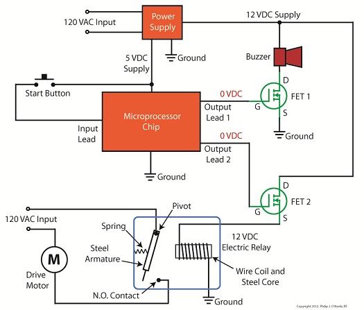
Last time we looked at my design solution for the control of a microprocessor controlled medical x-ray film developing machine, where a field effect transistor (FET) acted as a digital control interface between a 5 volt direct current (VDC) microprocessor and a 12 VDC buzzer. Well, controlling the buzzer wasn’t the only function of the microprocessor. It also had to control a 120 volt alternating current (VAC) drive motor, the purpose of which was to move x-ray film through a series of processes within the machine. Yet another requirement was that the machine’s drive motor run 40 minutes upon activation by a start button, then shut off. One of the challenges presented by this specification was that an FET standing alone is only suited to control direct current devices like the buzzer, but not alternating current devices like electric motors. Direct current flows in one direction only when traveling through wire, and since an FET can only pass current in one direction it is the perfect match for those applications. Now, as the name would imply, alternating current flow alternates, that is, it reverses direction and varies in intensity many times each second. This is a scenario that FETs are not equipped to handle because they can’t deal with reverse flow. This meant that, for the purpose of my developing machine, I could not use an FET to directly control the 120 VAC motor. Now let’s take a look at Figure 1 to get a basic look at how I solved the problem. |
Posts Tagged ‘machine control’
Transistors – Digital Control Interface, Part IV
Monday, July 9th, 2012Tags: 12 VDC, 120 VAC, alternating current, digital control, digital control interface, digital input, digital output, direct current, drain, drive motor, electric current, electric motor control, electric motors, electric relay, electrical ground, electronic device, engineering expert witness, FET, field effect transistor, forensic engineer, gate, machine control, microprocessor, microprocessor chip, output lead, pushbutton, relay coil, source, start button, transistor, x-ray film machine
Posted in Engineering and Science, Expert Witness, Forensic Engineering, Innovation and Intellectual Property, Personal Injury, Product Liability | 1 Comment »
Transistors – Digital Control Interface, Part III
Sunday, July 1st, 2012| When I was in engineering school in the mid 1970s microprocessor chips were still a fairly new concept. Scientific calculators were the size of a brick back then, and they weighed almost as much, and there were no personal computers.
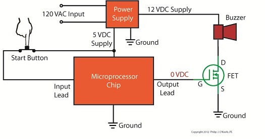
I remember doing homework on the UNIVAC 1108 mainframe computer at school. To program it I had to sit at a monster of a keypunching machine for which I punched an endless array of holes into paper cards. These holes acted as the programming logic to instruct the computer what functions to perform. The 1108 computer’s mainframe was so huge it was housed in an adjoining room the size of a house. Since the 1980s advances in microprocessor technology have increased computing power and dramatically reduced the size of components, making things like laptops, smart phones, and sophisticated electronic products possible. Last time we began looking at my design solution for the control of a machine which developed medical x-ray film and made use of a microprocessor chip to automate its operation. A field effect transistor (FET) acts as a digital control interface between its 5 volt direct current (VDC) microprocessor and a 12 VDC buzzer. Figure 1 shows what happens when someone presses the button to put everything into action and the microprocessor starts timing. Figure 1
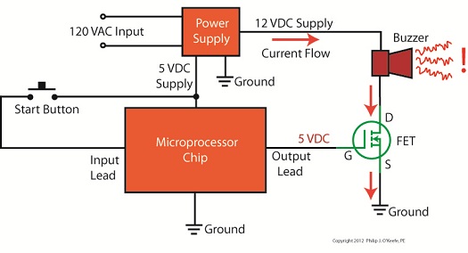
With the button depressed the chip senses 5 VDC from the power supply on its input lead. This in turn signals the computer program to turn the product on. The program then begins counting down the minutes, all the while maintaining a 0 voltage output from the chip’s output lead. With no voltage present on its G lead, the FET does not permit electrical current to flow from the 12 VDC supply, through the buzzer, through D and S, and down to electrical ground. The buzzer remains silent. Figure 2Figure 2 shows what happens when the program begins its 40-minute warming sequence. The chip raises the output lead voltage to 5 VDC and applies it to G, then the FET permits electric current to flow through it to ground from the 12 VDC supply and the buzzer. Now supplied with power, the buzzer sounds. Then, per programming instructions, after 2 seconds the program shuts off the voltage in the chip’s output lead, current is cut off, and the buzzer goes silent. Next time we’ll see how an FET can be used as an interface between a microprocessor and another higher powered device, that of a 120 VAC motor that’s used to move x-ray film through a series of processes within the developer.
____________________________________________ |
Tags: 12 VDC, 5 VDC, alarm, automate, buzzer, current, D, design solution, digital control, electric relay, electrical design, electronics, engineering expert witness, FET, field effect transistor, forensic engineer, G, hardware design, machine control, medical product, microprocessor chip, MOSFET, motor, power supply, programming logic, pushbutton, S, voltage
Posted in Engineering and Science, Expert Witness, Forensic Engineering, Innovation and Intellectual Property, Personal Injury, Product Liability | Comments Off on Transistors – Digital Control Interface, Part III
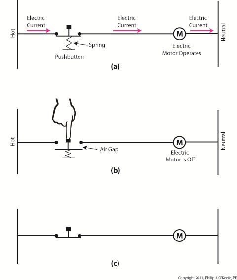
Industrial Control Basics – Pushbuttons
Monday, December 26th, 2011Tags: control system, current flow, electric motor, electrical circuit, engineering expert witness, forensic engineer, hot, industrial control, ladder diagram, machine control, mechanized equipment, motor control, neutral, normally closed, normally open, pushbutton, relay, spring, switch
Posted in Engineering and Science, Expert Witness, Forensic Engineering, Innovation and Intellectual Property, Personal Injury, Product Liability, Professional Malpractice | Comments Off on Industrial Control Basics – Pushbuttons
Industrial Control Basics
Sunday, December 4th, 2011| When I was a child in school I loved field trips. They didn’t happen too often, but when they did they were a welcomed break from the routine of the classroom. Once we went on a tour of a large factory that made telephones. During the tour we walked amongst gargantuan machines, conveyor belts, furnaces, boilers, pumps, and compressors, all energized and working together to transform raw materials into telephones. Sequences of manufacturing and assembly operations, from the simple to the most complex, were carefully orchestrated with no apparent human intervention.
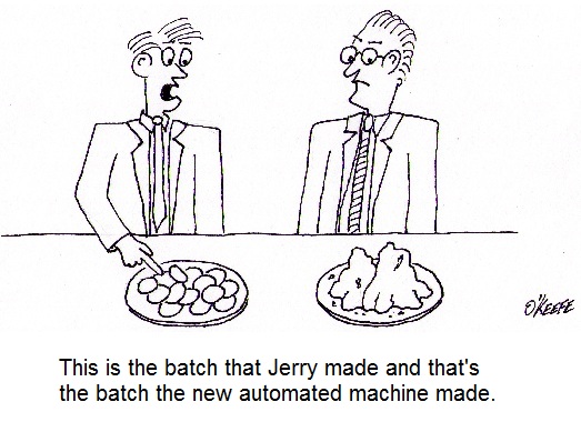
The equipment in the telephone factory was certainly impressive to watch, and our tour guides did a fine job of explaining what was happening, except for one important detail. I realized after we left that no one had explained who or what was actually controlling the machinery. I realized even then that machines can’t think for themselves. They can only do what humans tell them to do. I didn’t know it at the time, but the telephone factory setup included some interesting examples of industrial control systems. Industrial control systems can be broken down into two basic categories, manual controls and automatic controls. Manual controls work as their name implies, that is, someone must manually press a button or throw a switch to initiate factory operations. This involves continual monitoring of processes, coupled with hands-on activities to keep everything working. Automatic controls still require human intervention to some extent, such as initiating operations, but once that’s done they move into self-regulation mode until the operations are shut down at the end of production. Employees are thus freed up to spend time doing things which are not automated. Automatic controls are excellent at handling mundane, repetitive tasks that humans tend to get quickly bored with. Boredom leads to a lack of attention, and this may lead to accidents, so utilizing automatic controls often makes for a safer work environment. Next time we’ll begin our examination of how manual and automatic controls work within the context of an industrial setting. To begin, we’re going to take a virtual field trip back to the telephone factory and look at some basic industrial control examples. ____________________________________________
|
Tags: accidents, automatic control, boilers, button, compressors, controlling machinery, conveyor belt, engineering expert witness, factory, forensic engineer, furnaces, industrial control, machine control, machines, manual control, process monitoring, pumps, switch, telephones
Posted in Engineering and Science, Expert Witness, Forensic Engineering, Innovation and Intellectual Property, Personal Injury, Product Liability, Professional Malpractice | Comments Off on Industrial Control Basics
