| When I was in engineering school in the mid 1970s microprocessor chips were still a fairly new concept. Scientific calculators were the size of a brick back then, and they weighed almost as much, and there were no personal computers.
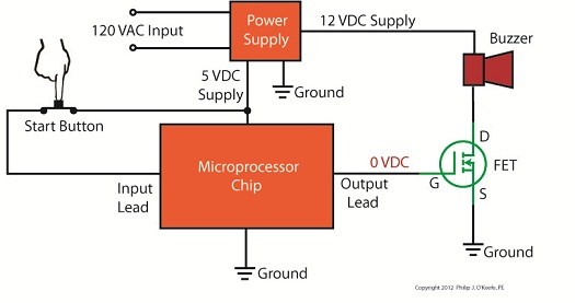
I remember doing homework on the UNIVAC 1108 mainframe computer at school. To program it I had to sit at a monster of a keypunching machine for which I punched an endless array of holes into paper cards. These holes acted as the programming logic to instruct the computer what functions to perform. The 1108 computer’s mainframe was so huge it was housed in an adjoining room the size of a house. Since the 1980s advances in microprocessor technology have increased computing power and dramatically reduced the size of components, making things like laptops, smart phones, and sophisticated electronic products possible. Last time we began looking at my design solution for the control of a machine which developed medical x-ray film and made use of a microprocessor chip to automate its operation. A field effect transistor (FET) acts as a digital control interface between its 5 volt direct current (VDC) microprocessor and a 12 VDC buzzer. Figure 1 shows what happens when someone presses the button to put everything into action and the microprocessor starts timing. Figure 1
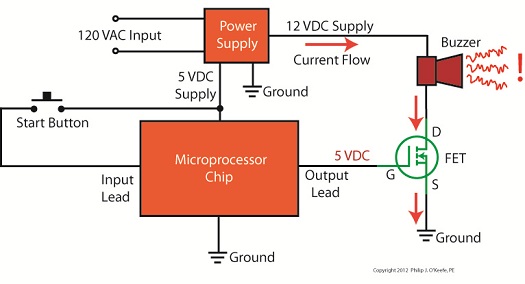
With the button depressed the chip senses 5 VDC from the power supply on its input lead. This in turn signals the computer program to turn the product on. The program then begins counting down the minutes, all the while maintaining a 0 voltage output from the chip’s output lead. With no voltage present on its G lead, the FET does not permit electrical current to flow from the 12 VDC supply, through the buzzer, through D and S, and down to electrical ground. The buzzer remains silent. Figure 2Figure 2 shows what happens when the program begins its 40-minute warming sequence. The chip raises the output lead voltage to 5 VDC and applies it to G, then the FET permits electric current to flow through it to ground from the 12 VDC supply and the buzzer. Now supplied with power, the buzzer sounds. Then, per programming instructions, after 2 seconds the program shuts off the voltage in the chip’s output lead, current is cut off, and the buzzer goes silent. Next time we’ll see how an FET can be used as an interface between a microprocessor and another higher powered device, that of a 120 VAC motor that’s used to move x-ray film through a series of processes within the developer.
____________________________________________ |
Posts Tagged ‘medical product’
Medical Device Design Controls – Transfer, Changes, and History
Sunday, September 12th, 2010| Did you ever hear the saying, “garbage in, garbage out?” Perhaps you’ve used it yourself at times, as when your teenager insists on writing their 20-page term paper the night before it’s due. Parents, having the benefit of decades of life experience, know that the outcome of a last ditch effort of this type will most likely not turn out well.
This wisdom also applies particularly well to the medical manufacturing process. The FDA is like the parent in this instance, mandating that Design Transfer Procedures be in place to avert the types of disasters which might ensue if the “garbage” philosophy were carried out. Meant to ensure that medical device designs are correctly translated into production specifications for manufacturing, Design Transfer Procedures keep those directly involved with the manufacturing process in check. It is absolutely vital that those involved in manufacturing receive accurate and complete information. Imagine what would happen if an engineer provided a manufacturer with faulty design information. Components could be made to the wrong specifications or of a material that proves toxic to the application. These errors range in negative effect from being costly in terms of dollars wasted to perhaps costing someone their life. A Design Transfer Procedure would ensure that a variety of mishaps do not occur during the transfer process. The procedure is typically overseen by the medical device company’s management. For example, a Design Transfer Procedure would lay out responsibilities of supervisors and managers to make sure the latest revision of electrical schematics, bills of materials, Gerber files, and quality testing procedures are received by the manufacturer of a device’s printed circuit boards. It’s important that the order is received in a timely manner so as not to hold up the manufacturing process. However, it’s much more important that the printed circuit board is made properly, the correct electrical components are placed on it in the correct orientation, and it is tested to make sure it doesn’t malfunction after assembly. Design Change Procedures basically ensure that when changes are necessary, the medical device company follows all the procedures for Design and Development Planning, Design Input, Design Output, Design Review, Design Verification, and Design Validation. Once the changes are reviewed, validated, verified, and approved, they can be incorporated into the original device design. This is where the Design Change Procedure must dovetail with the Design Transfer Procedure to make sure the correct information is provided to the company’s management staff in the procurement, manufacturing, product service, and warehouse departments. This is to make sure they can keep component vendors on track with the changes, maintain sufficient inventory of the changed components, put the right components in the device during assembly, and properly support repair technicians in the field. Yet another aspect of Design Controls promulgated by the FDA comes into play with the establishment of procedures for maintaining a Design History File (DHF). This DHF contains all documentation created during the life cycle of the project, meaning, movement from creation to completion and on into market introduction, sometimes beyond. DHF Procedure sets up protocols for collection and organization of information about the medical device design, starting with design documentation and covering the gamut from design changes, to validation testing, to design verification, and on to design review. All this is done to ensure that the initial product design was developed in accordance with the original design plan and overall product design requirements. _____________________________________________ |


