Posts Tagged ‘electric motors’

Simple Pulleys

Tuesday, June 28th, 2016

    Pulleys are simple devices with many uses, and as an engineering expert, I’ve often incorporated them into mechanical designs.   They’re used in machinery to transmit mechanical power from electric motors and engines to devices like blowers and pumps.   Another common usage for pulleys is to aid in lifting.   There are two types of pulleys for this purpose, simple or compound. We’ll start our discussion off by looking at the simple type today.

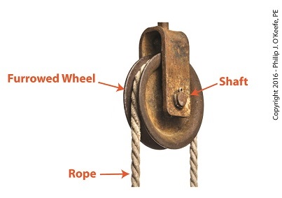
    The simple pulley may have been an advanced application of the wheel.   It consists of a furrowed wheel on a shaft with some device for pulling threaded through it.   The pulley wheel supports and guides the movement of a rope, cable, or other pulling device around its circumference.   The pulling device runs between a pull-ee and pull-er, that is, the object to be moved and the source of pulling power, with the pulley itself situated somewhere between them.

The Simple Pulley

Simple Pulley

    Pulleys are believed to have first been used by the Greeks as early as the 9th Century BC.   We’ll look into how they put them to use next time.

Copyright 2016 – Philip J. O’Keefe, PE

Engineering Expert Witness Blog

____________________________________


Work and Energy Share an Interesting Relationship

Thursday, December 10th, 2015

      My work as an engineering expert has often required that I perform calculations to quantify the energy consumed by electric motors and steam turbines, such as when they work together at power plants to generate electricity.   Today we’ll see how work and energy share an interesting relationship that is brought out by examining the units by which they are measured.

     Last time we used de Coriolis’ formula to compute work to calculate the amount of work performed while pushing a loaded wheelbarrow a distance of 3 meters.   We found that in order to move the wheelbarrow that distance, a gardener must exert a force equal to 534 Newton • meters of work.   That relationship is shown here,

Work = 178 Newtons × 3 meters = 534 Newton • meters           (1)


Work is force times distance

de Coriolis’ Formula to Compute Work


     The Newton, as discussed previously in this blog series, is shorthand notation for metric units of force, and we’ll use those units today to demonstrate the special relationship between work and energy.

We’ll start by supposing that you’re unfamiliar with the Newton as a unit of measurement.   In that case you’d have to employ longhand notation to quantify things, which means you’d be measuring units of force in terms of kilogram • meters per second2.

     Putting equation (1) in longhand notation terms, we arrive at,

Work = 178 kilogram • meters per second2 × 3 meters       (2)

Work = 534 kilogram • meters2 per second2                    (3)

     If you’ve been following along in this blog series, you’ll recognize that the unit of measurement used to compute work, namely, kilogram • meters2 per second2, is the same as was used previously to measure energy.  That unit is the Joule, which is considerably less wordy.

     Equations (2) and (3) bear out the interesting relationship between work and energy — they share the same unit of measure.   This relationship would not be apparent if we only considered the units for work presented in equation (1).

     So following standard engineering convention where work and energy are expressed in the same units, the work required to push the wheelbarrow is expressed as,

Work = 534 Joules

     Yes, work and energy are measured by the same unit, the Joule.   But, energy isn’t the same as work.   Energy is distinguished from work in that it’s the measure of the ability to perform work.    Stated another way, work cannot be performed unless there is energy available to do it, just as when you eat it provides more than mere pleasure, it provides your body with the energy required to perform the work of pushing a wheelbarrow through the garden.

     Next time we’ll see how work factors into the Work Energy Theorem, which mathematically relates work to energy.

Copyright 2015 – Philip J. O’Keefe, PE

Engineering Expert Witness Blog

____________________________________


Transistors – Digital Control Interface, Part IV

Monday, July 9th, 2012
     The Olympic Torch relay, soon to culminate in London, is the grand daddy of all relays, starting in one country, traversing many others, then ending its journey at the site of the Olympic Games.  It passes through many athletes’ hands while on its journey, its final purpose being to light the Olympic Flame.  Less glamorous, though still useful, is the relay race that often takes place within digital controls.

      Last time we looked at my design solution for the control of a microprocessor controlled medical x-ray film developing machine, where a field effect transistor (FET) acted as a digital control interface between a 5 volt direct current (VDC) microprocessor and a 12 VDC buzzer.  Well, controlling the buzzer wasn’t the only function of the microprocessor.  It also had to control a 120 volt alternating current (VAC) drive motor, the purpose of which was to move x-ray film through a series of processes within the machine.  Yet another requirement was that the machine’s drive motor run 40 minutes upon activation by a start button, then shut off.

     One of the challenges presented by this specification was that an FET standing alone is only suited to control direct current devices like the buzzer, but not alternating current devices like electric motors.  Direct current flows in one direction only when traveling through wire, and since an FET can only pass current in one direction it is the perfect match for those applications.  

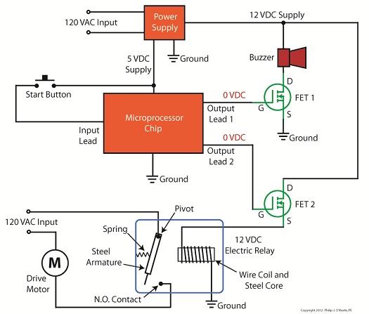
     Now, as the name would imply, alternating current flow alternates, that is, it reverses direction and varies in intensity many times each second.  This is a scenario that FETs are not equipped to handle because they can’t deal with reverse flow.  This meant that, for the purpose of my developing machine, I could not use an FET to directly control the 120 VAC motor.  Now let’s take a look at Figure 1 to get a basic look at how I solved the problem.

microprocessor electric relay control

Figure 1 


     Figure 1 shows not one, but two green FET’s, each branching off from the microprocessor chip.  We’ll call them FET 1 and FET 2.  If you recall from last time, the buzzer works on 12 VDC, so FET 1 works well as a direct interface between it and the microprocessor chip.  But in the case of FET 2 we need an intermediary device to handle the alternating current motor.  That device is a 12 VDC electric relay.

     In an earlier blog series on industrial controls I discussed how electric relays use electromagnets to power light bulbs and motors on and off in response to someone pressing a button on a control panel.  We have very much the same mechanics at play in our developing machine.  The relay will power the motor on and off in response to the computer program running within the 5 VDC microprocessor, a programming sequence that is initiated by someone pressing a button. 

     To get the motor control to work in the machine, the gate (G) of FET 2 is connected to another output lead on the microprocessor.  We’ll call that Output Lead 2.  Then, the source (S) of FET 2 is connected to the wire coil in the relay.  To tap into the power source for the relay, the drain (D) of FET 2 is connected to the 12 VDC supply.   Finally, the other end of the relay coil is connected to electrical ground.

     Next time we’ll activate the pushbutton and see how the control initiative passes along a path in a manner reminiscent of the flame in an Olympic Torch relay, but here it passes between the microprocessor, the FET and electrical relay, culminating in power to the drive motor.

 ____________________________________________