|
Last week we explored the topic of thermal expansion, and we learned how the bimetal contacts in a motor overload relay distort when heated. We also discussed how the overload relay comes into play to prevent overheating in electric motor circuits. Now let’s see what happens when an overload situation occurs. Figure 1
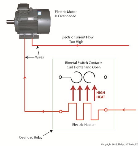
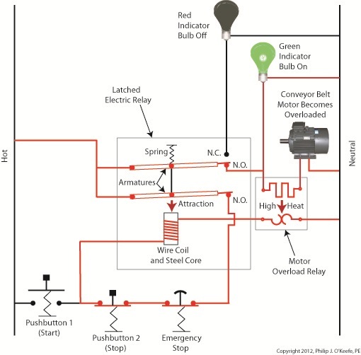
Figure 1 shows a motor becoming overloaded, as it draws in abnormally high amounts of electric current. Since this current also flows through the electric heater in the overload relay, the heater starts producing more heat than it would if the motor were running normally. This abnormally high heat is directed towards the bimetal switch contacts, causing them to curl up tightly until they no longer touch each other and open up. They will only close again when the overload condition is cleared up and the heater cools back down to normal operating temperature. Let’s now take a look at Figure 2 to see how the motor overload relay fits into our example of a conveyor belt motor control circuit. Once again, the path of electric current flow is denoted by red lines. Figure 2
The circuit in Figure 2 represents what happens after Button 1 is depressed. That is, the electric relay has become latched and current flows between hot and neutral sides through one of the N.O. contacts along the path of the green indicator bulb, the motor overload relay heater, and the conveyor belt motor. The current also flows through the other N.O. contact, the Emergency Stop button, Button 2, the electric relay’s wire coil, and the motor overload relay bimetal contacts. The motor becomes overloaded, causing the overload relay heater to produce abnormally high heat. This heat is directed towards the bimetal contacts, also causing them to heat up. Figure 3
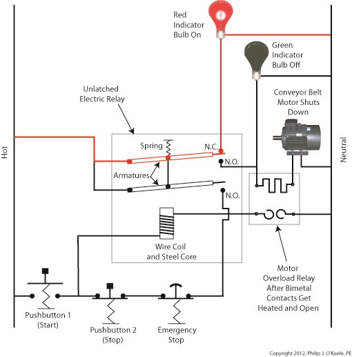
In Figure 3 the bimetal contacts have heated to the point that they have curled away from each other until they no longer touch. With the bimetal contacts open, electric current is unable to flow through to the electric relay’s wire coil. This in turn ends the magnetic attraction which formerly held the relay armatures against the N.O. contacts. The spring in the electric relay has pulled the armatures up, causing the N.O. contacts to open, simultaneously closing the N.C. contact. These actions have resulted in a loss of current to the green indicator bulb and electric motor. The red indicator bulb is now activated, and the conveyor motor is caused to automatically shut down to prevent damage and possible fire due to overheating. This means that even if the conveyor operator were to immediately press Button 1 in an attempt to restart the line, he would be prevented from doing so. Under these conditions the electric relay is prevented from latching, and the motor remains shut down because the bimetal contacts have been separated, preventing current from flowing through to the wire coil. The bimetal contacts will remain open until they once again cool to normal operating temperature. Once cooled, they will once again close, and the motor can be restarted. If the cause of the motor overload is not diagnosed and its ability to recur eliminated, the automatic shutdown process will repeat this cycle. Next time we’ll see how the overload relay is represented in a ladder diagram. We’ll also see how switches can be added to the circuit to allow maintenance staff to safely work. ____________________________________________
|
Posts Tagged ‘automatic control’
Industrial Control Basics – Motor Overload Relay In Action
Sunday, March 18th, 2012Tags: automatic control, bimetalic contacts, closed contact, controls engineer, electric current, electric relay, emergency stop, engineering expert witness, fire, forensic engineer, heater, hot, indicator bulb, industrial control, motor control, motor damage, motor overload, motor overload relay, N.C. contact, N.O. contact, neutral, normally closed contact, normally open contact, open contact, pushbutton
Posted in Engineering and Science, Expert Witness, Forensic Engineering, Innovation and Intellectual Property, Personal Injury, Product Liability, Professional Malpractice | Comments Off on Industrial Control Basics – Motor Overload Relay In Action
Industrial Control Basics – Thermal Expansion Effect on Overload Relays
Sunday, March 11th, 2012| Imagine driving on steel tires, not rubber. Don’t think it would work too well? On asphalt highways maybe not, but on the steel rails that steam locomotives travel upon, steel wheels work surprisingly well and it’s due in large part to the principles of thermal expansion and the different rates at which metal alloys expand and contract. Allow me to explain by analyzing how a locomotive“tire” is changed.
As you can imagine changing locomotive tires isn’t easy. Firstly, locomotive shop mechanics have to actually build a fire around the steel tire to heat it up. The intense heat causes its steel tire to thermally expand, meaning its steel molecules become energized by the heat and begin to vibrate. This causes the molecules to move away from each other, and this results in the tire actually growing slightly in size. This enlargement is just enough to enable mechanics to slip the tire back onto the locomotive’s wheel. Now in place, the tire is allowed to cool back down to ambient air temperatures. Cooling results in the tire’s steel molecules relaxing and moving closer to each other. The tire shrinks back to its original preheated size and tightly wraps itself around the wheel. Thermal expansion properties of metals comes into play in many other instances, including the workings of motor overload relays. Please refer to Figure 1. Figure 1
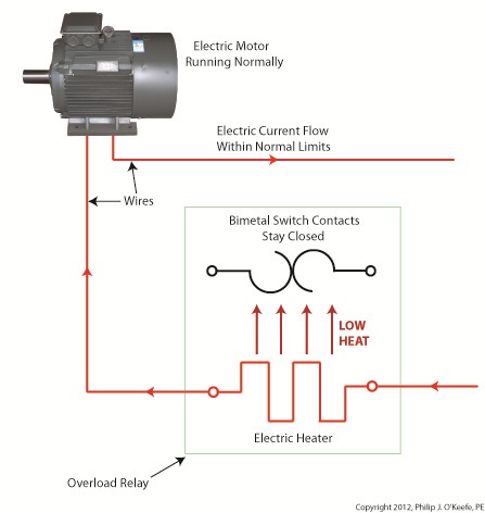
Here overload relay components are shown in the foreground box. We see that the relay includes an electric heater and a set of two peculiar looking curved objects. These are bimetal switch contacts, so named because each is made of two, that’s the “bi” part, metal strips with different thermal properties. These strips are positioned back to back, then bonded together and curved into a shape resembling a question mark. Each of the two metals has different properties, namely, one expands at a faster rate and to a greater extent than the other when heated. This differing rate of expansion is indicative of the two metals’ diverse thermal properties. When the bimetal contact is exposed to heat, one metal strip wants to expand a lot, but it is bonded to the other metal strip which only wants to expand a little. The end result is that their point of contact distorts and changes shape. When allowed to cool back down, the metal strips contract and the contact point returns to its original shape. In our next blog we’ll see how the contact shape changes and why this shape change is important. In Figure 1 the motor is running normally and there is no overload situation. Under these conditions the motor draws electric current within the normal limits of its design. That current also flows through the heater in the overload relay causing it to generate heat, but in this situation the heat change is small enough that it doesn’t affect the bimetal switch contacts and cause them to change shape. The temperature at which the switch contacts will warp depends on the overall design of the overload relay as well as its application. Next time we’ll see what part a motor overload plays in conjunction with the overload relay’s heater and bimetal contacts. ____________________________________________
|
Tags: automatic control, bimetalic contact, contract, electric current, electrical contacts, engineering expert witness, expand, forensic engineer, heater, industrial control, locomotive, locomotive tire, metal alloys, motor control, motor overload, motor overload relay, relay, steel tire, switch contacts, thermal expansion, wheel
Posted in Engineering and Science, Expert Witness, Forensic Engineering, Innovation and Intellectual Property, Personal Injury, Product Liability, Professional Malpractice | Comments Off on Industrial Control Basics – Thermal Expansion Effect on Overload Relays
Industrial Control Basics – Ladder Diagrams
Sunday, December 18th, 2011| The other day I pressed the button to activate my electric garage door opener and nothing happened. I pushed again and again, still nothing. Finally, I convinced myself to get out of the car and take a closer look. A wooden board I had propped up against the side of the garage wall had come loose, wedging itself in front of the electric eye, you know, the one that acts as a safety. The board was an obstruction to the clear vision of the eye. It couldn’t see the light emitter on the other side of the door opening and wouldn’t permit the door opener to function.
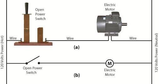
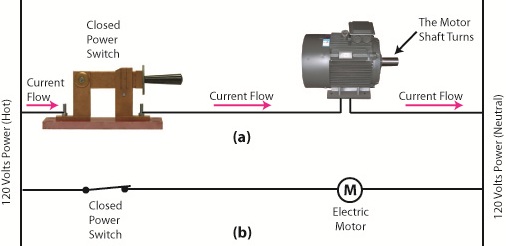
The basic manual control system we looked at last week operates similarly to the eye on a garage door opener. If you can’t “close the loop,” you won’t get the power. Last week’s example was as basic as things get. Now let’s look at something a bit more complex. Words aren’t always the best vehicle to facilitate understanding, which is why I often use visual aids in my work. In the field of industrial control systems diagrams are often used to illustrate things. Whether it’s by putting pencil to paper or the flow diagram of software logic, illustrations make things easier to interpret. Diagrams such as the one in Figure l are often referred to as “ladder diagrams,” and in a minute we’ll see why. Figure 1 Figure 1(a) shows a basic manual control system. It consists of wires that connect a power switch and electric motor to a 120 volt alternating current power source. One wire is “hot,” the other “neutral.” The hot side is ungrounded, meaning that it isn’t electrically connected to the Earth. The neutral side is grounded, that’s right, it’s driven into the ground and its energy is dissipated right into the earth, then returned back to the power grid. In Figure 1(a) we see that the power switch is open and an air gap exists. When gaps exist, we don’t have a closed electrical loop, and electricity will not flow. Figure 1(b), our ladder diagram, aka line diagram, shows an easier, more simplified representation of the manual control shown in Figure 1(a). It’s easier to decipher because there’s less going on visually for the brain to interpret. Everything has been reduced to simple lines and symbols. For example, the electric motor is represented by a symbol consisting of a circle with an “M” in it. Now, let’s turn our attention to Figure 2 below to see what happens when the power switch is closed. Figure 2 The power switch in Figure 2(a) is closed, allowing electric current to flow between hot and neutral wires, then power switch, and finally to the motor. The current flow makes the motor come to life and the motor shaft begins to turn. The line diagram for this circuit is shown in Figure 2(b). You might have noticed that the line diagrams show in Figures 1(b) and 2(b) have a rather peculiar shape. The vertically running lines at either side depict the hot and neutral legs of the system. If you stretch your imagination a bit, they look like the legs of a ladder. Between them run the wires, power switch, and motor, and this horizontal running line represents the rung of the ladder. More complicated line diagrams can have hundreds, or even thousands of rungs, making up one humongous ladder, hence they are commonly referred to as ladder diagrams. Next week we’ll take a look at two key elements in automatic control systems, the push button and electric relay, elements which allow us to do away with the need for human intervention. ____________________________________________ |
Tags: automatic control, electric circuit, electric current, electric motor, electric relay, electric utility, engineering expert witenss, forensic engineer, ground, hot, industrial control, ladder diagram, ladder logic, line diagram, manual control, motor control, neutral, power flow, power grid, power switch, push button, visual aid, wires
Posted in Courtroom Visual Aids, Engineering and Science, Expert Witness, Forensic Engineering, Innovation and Intellectual Property, Personal Injury, Product Liability, Professional Malpractice | Comments Off on Industrial Control Basics – Ladder Diagrams
Industrial Control Basics
Sunday, December 4th, 2011| When I was a child in school I loved field trips. They didn’t happen too often, but when they did they were a welcomed break from the routine of the classroom. Once we went on a tour of a large factory that made telephones. During the tour we walked amongst gargantuan machines, conveyor belts, furnaces, boilers, pumps, and compressors, all energized and working together to transform raw materials into telephones. Sequences of manufacturing and assembly operations, from the simple to the most complex, were carefully orchestrated with no apparent human intervention.
The equipment in the telephone factory was certainly impressive to watch, and our tour guides did a fine job of explaining what was happening, except for one important detail. I realized after we left that no one had explained who or what was actually controlling the machinery. I realized even then that machines can’t think for themselves. They can only do what humans tell them to do. I didn’t know it at the time, but the telephone factory setup included some interesting examples of industrial control systems. Industrial control systems can be broken down into two basic categories, manual controls and automatic controls. Manual controls work as their name implies, that is, someone must manually press a button or throw a switch to initiate factory operations. This involves continual monitoring of processes, coupled with hands-on activities to keep everything working. Automatic controls still require human intervention to some extent, such as initiating operations, but once that’s done they move into self-regulation mode until the operations are shut down at the end of production. Employees are thus freed up to spend time doing things which are not automated. Automatic controls are excellent at handling mundane, repetitive tasks that humans tend to get quickly bored with. Boredom leads to a lack of attention, and this may lead to accidents, so utilizing automatic controls often makes for a safer work environment. Next time we’ll begin our examination of how manual and automatic controls work within the context of an industrial setting. To begin, we’re going to take a virtual field trip back to the telephone factory and look at some basic industrial control examples. ____________________________________________
|
Tags: accidents, automatic control, boilers, button, compressors, controlling machinery, conveyor belt, engineering expert witness, factory, forensic engineer, furnaces, industrial control, machine control, machines, manual control, process monitoring, pumps, switch, telephones
Posted in Engineering and Science, Expert Witness, Forensic Engineering, Innovation and Intellectual Property, Personal Injury, Product Liability, Professional Malpractice | Comments Off on Industrial Control Basics
