Posts Tagged ‘control system’
Monday, January 9th, 2012
| It’s a dark and stormy night and you’ve come to the proverbial fork in the road. The plot is about to take a twist as you’re forced to make a decision in this either/or scenario. As we’ll see in this article, an electric relay operates in much the same manner, although choices will be made in a forced mechanical environment, not a cerebral one.
When we discussed basic electric relays last week we talked about their resting in a so-called “normal state,” so designated by industrial control parlance. It’s the state in which no electric current is flowing through its wire coil, the coil being one of the major devices within a relay assembly. Using Figure 3 of my previous article as a general reference, in this normal state a relaxed spring keeps the armature touching the N.C. switch contact. While in this state, a continuous conductive path is created for electricity through to the N.C. point. It originates from the wire on the left side, which leads to the armature pivot point, travels through the armature and N.C. contact points, and finally dispenses through the wire at the right leading from the N.C. contact.
Now let’s look at an alternate scenario, when current is made to flow through the coil. See Figure l, below.

Figure 1
Figure 1 shows the path of electric current as it flows through the wire coil, causing the coil and the steel core to which it’s attached to become magnetized. This magnetization is strong, attracting the steel armature and pulling it towards the steel core, thus overcoming the spring’s tension and its natural tendency to rest in a tension-free state.
The magnetic attraction causes the armature to rotate about the pivot point until it comes to rest against the N.O. contact, thus creating an electrical path en route to the N.O. wire, on its way to whatever device it’s meant to energize. As long as current flows through the wire coil, its electromagnetic nature will attract the armature to it and contact will be maintained with the N.O. juncture.
When current is made to flow through the wire coil, an air gap is created between the armature and the N.C. contact, and this prevents the flow of electric current through the N.C. contact area. Current is forced to follow the path to the N.O. contact only, effectively cutting off any other choice or fork in the road as to electrical path that may be followed. We can see that the main task of an electric relay is to switch current between two possible paths within a circuit, thereby directing its flow to one or the other.
Next time we’ll examine a simple industrial control system and see how an electric relay can be engaged with the help of a pushbutton.
____________________________________________ |
Tags: armature, coil, control relay, control system, current flow, electric current, electric relay, electrical path, electrical relay, electrical switch, electricity, electromagnetic, engineering expert witness, forensic engineering, industrial control, magnetic attraction, N.C., N.C. contact, N.O., N.O. contact, normal state, normally closed, normally open, pushbutton, relay, relay ladder logic, spring, steel core, switch, switch contact, switching current, wire coil
Posted in Engineering and Science, Expert Witness, Forensic Engineering, Innovation and Intellectual Property, Personal Injury, Product Liability, Professional Malpractice | 1 Comment »
Tuesday, January 3rd, 2012
| I’ve always considered science to be cool. Back in the 5th grade I remember fondly leafing through my science textbook, eagerly anticipating our class performing the experiments, but we never did. For some reason my teacher never took the time to demonstrate any. Undeterred, I proceeded on my own.
I remember one experiment particularly well where I took a big steel nail and coiled wire around it. When I hooked a battery up to the wires, as shown in Figure 1 below, electric current flowed from the battery through the wire coil. This set up a magnetic field in the steel nail, thereby creating an electromagnet. My electromagnet was strong enough to pick up paper clips, and I took great pleasure in repeatedly picking them up, then watching them unattach and fall quickly away when the wires were disconnected from the battery.
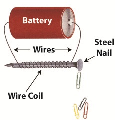
Figure 1
Little did I know then that the electromagnet I had created was similar to an important part found within electrical relays used in many industrial control systems. An example of one of these relays is shown in Figure 2.

Figure 2
So, what’s in the little plastic cube? Well, a relay is basically an electric switch, similar to the ones we’ve discussed in the past few weeks, the major difference being that it is not operated directly by human hands. Rather, it’s operated by an electromagnet. Let’s see how this works by examining a basic electrical relay, as shown in Figure 3.
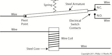
Figure 3
The diagram in Figure 3 shows a basic electric relay constructed of a steel core with a wire coil wrapped around it, similar to the electromagnet I constructed in my 5th grade experiment. If the coil’s wires are not hooked up to a power source, a battery for example, no electric current will flow through it. When there is no current the coil and steel core are not magnetic. For purposes of our illustration and in accordance with industrial control parlance, this is said to be this relay’s “normal state.”
Next to the steel core there is a movable steel armature, a kind of lever, which is attached to a spring. On one end of the armature is a pivot point, on the other end is a set of electrical switch contacts. When the relay is in its normal state, the spring’s tension holds the armature against the “normally closed,” or N.C., contact. If electric current is applied to the wire leading to the pivot point on the armature while in this state, it will be caused to flow on a continuous path through the armature and the N.C. contact, then out through the wire leading from the N.C. contact. In our illustration, since the armature does not touch the N.O. contact, an air gap is created that prevents electric current from traveling through the contact from the armature.
Next week we’ll see how these parts come into play within a relay when electric current flows through the coil, turning it into an electromagnet.
____________________________________________ |
Tags: armature, control system, electric current, electric relay, electrical switch contacts, electromagnet, electromechanical relay, engineering expert witness, forensic engineer, industrial control, magnet, magnetic steel core, normal state, normally closed, normally open, power, relay, relay logic, spring, steel core, switch, switch contact, wire, wire coil
Posted in Engineering and Science, Expert Witness, Forensic Engineering, Innovation and Intellectual Property, Personal Injury, Product Liability, Professional Malpractice | Comments Off on Industrial Control Basics – Introduction to Electric Relays
Monday, December 26th, 2011
| I always enjoy watching impatient people waiting for an elevator. They press the button, and if it doesn’t come within a few seconds they press it over and over again, as if this will hurry things up. In the end they must resign themselves to the fact that the elevator will operate in its own good time.
Pushbuttons, although simple in appearance like the big, red “Easy” button that’s featured in a certain business supply chain’s commercials, are actually complex behind the scenes. They perform important functions within the industrial control systems of a huge diversity of mechanized equipment.
Last week we introduced ladder diagrams, used to design and document industrial control systems, and we’ll now see how they depict the action of pushbuttons within two commonly used industrial settings, the “normally open” and the “normally closed.”
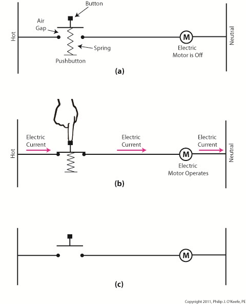
Figure 1
Figure 1(a) shows a pushbutton hooked up to an electric motor. When no one is pressing it a spring in the pushbutton forces the button to rest in the up position, allowing an air gap to exist in the electrical circuit between hot and neutral and preventing current from flowing. This type of switch is characterized as a “normally open” switch in industrial control terminology.
In Figure 1(b) someone depresses the button, compressing its spring and closing the air gap, which allows current to flow and the motor to operate
Figure 1(c) shows the ladder diagram version of 1(a).
Now let’s take a look at Figure 2 to see a different type of pushbutton, one that’s characterized as “normally closed.”
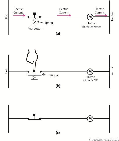 Figure 2 Figure 2
“Normally closed” refers to the fact that when no one is depressing the button, the normal operating position is for the air gap to be absent, allowing electrical current to flow and the motor to operate, as shown in Figure 2(a).
Figure 2(b) shows that an air gap is created when the button is depressed and the spring holding the mechanism into the normally closed position is forced down. This action interrupts electrical current and causes the motor to stop.
Figure 2(c) shows the simplified line drawing version of 2(a).
You can imagine how strained your finger would be if it had to press down on that button with any frequency or duration. Next time we’ll see how electrical relays work alongside pushbuttons to give index fingers a break.
____________________________________________ |
Tags: control system, current flow, electric motor, electrical circuit, engineering expert witness, forensic engineer, hot, industrial control, ladder diagram, machine control, mechanized equipment, motor control, neutral, normally closed, normally open, pushbutton, relay, spring, switch
Posted in Engineering and Science, Expert Witness, Forensic Engineering, Innovation and Intellectual Property, Personal Injury, Product Liability, Professional Malpractice | Comments Off on Industrial Control Basics – Pushbuttons
Monday, December 12th, 2011
| You’ve probably heard the saying, “asleep at the switch.” It’s usually associated with some sort of disaster, found later to have been caused by human error. Someone wasn’t paying attention, and something very bad happened. The meltdown of the Soviet nuclear power plant Chernobyl in 1986 comes to mind. You may be surprised to learn that the saying has its origins in the world of industrial controls, or more specifically, manual controls, as we’ll see in this article.
Last week when we opened our discussion on manual controls, we talked about how they work just as their name implies, that is, someone must manually press a button or throw a switch in order to initiate a factory operation. In other words, a manual control requires human intervention to initiate an action, such as pushing the start button. The machine will then continue to run until a person hits the stop button.
Let’s go now on a virtual field trip into a telephone factory to see how a basic manual control system works. It has a conveyor belt operated by an electric motor, and this motor is connected by wires and a power switch to a 120 volt power source of alternating current. Figure 1 illustrates what we mean. It shows that when the power switch is in the open position, a physical air gap exists within the electrical circuit. This prevents electricity from flowing through the wire because electricity can’t jump over gaps.
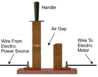
Figure 1 – Open Power Switch
Enter a human into the scenario, someone who grabs the power switch handle and manually closes it, eliminating the air gap. See Figure 2.
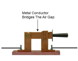
Figure 2 – Closed Power Switch
When the power switch is closed, a metal conductor bridges the gap, causing electricity to flow through the metal conductor to the electric motor in the circuit. This brings life to the conveyor belt. As long as the power switch remains closed, the conveyor belt will continue to operate.
That’s it, that’s a basic manual control system. It’s simple to operate, but it does have one major flaw. It requires constant monitoring by a human. Aside from opening and closing a power switch, humans are required to monitor operations, in case something goes wrong. The operator watching over an industrial machine performs the same function as the pilot on a plane, that is, to start-stop operations, and to intervene in case of an emergency. Computers fly modern jets. Pilots serve as trouble shooters when the unanticipated disaster situation occurs, because computers can’t yet creatively problem solve.
Next time we’ll introduce the element of an automatic control system, which will virtually eliminate the need for human intervention and with it human error.
____________________________________________ |
Tags: air gap, alternating current, asleep at the switch, assembly line, control system, conveyor belt, electricity, electricity flow, engineering expert witness, factory, forensic engineer, industrial controls, machine, manual control, metal conductor, motor, operator, power plant, power source, power switch, production line, start button, stop button, telephone, wire
Posted in Engineering and Science, Expert Witness, Forensic Engineering, Innovation and Intellectual Property, Personal Injury, Product Liability, Professional Malpractice | Comments Off on Industrial Control Basics – Manual Control


