Posts Tagged ‘coil’
Monday, July 23rd, 2018
|
So far in this series of articles, we have talked about pneumatic actuators that move jelly filling through a depositor on a pastry production line in a food manufacturing plant. These actuators have pistons with piston rods that create linear motion. The direction of this motion depends on which side compressed air is admitted to the piston inside the actuator. Now, let’s begin discussing a device known to engineers as a solenoid valve. These valves are used to selectively admit compressed air to either side of the pneumatic actuator’s piston, and thus, change the direction of the actuator’s linear motion.
As a solenoid valve’s name implies, a key component is a solenoid. A solenoid consists of a tube, having a coil of wire wrapped around its exterior. Electrical wires extend from the coil to an electrical switch and a voltage supply of, for example, 120 Volts. Inside the tube, there is a steel plunger that is free to move. When the switch is open, the coil is de-energized. That is, no electric current flows from the voltage supply through the coil of wire.
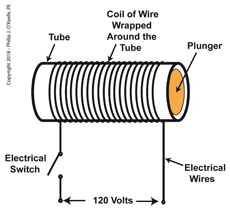
A De-Energized Solenoid
When the electrical switch is closed, the coil becomes energized. As electrical current flows through the coil, a magnetic field is created in the tube. This field forces the steel plunger out of the tube. The magnetic field and force on the plunger remain as long as the switch is closed.
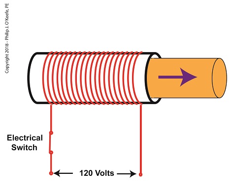
An Energized Solenoid
A solenoid valve consists of a solenoid that is attached to a metal valve body. The solenoid is typically enclosed in a plastic or metal housing. The valve body contains various ports. The ports are threaded holes for the connection of compressed air pipes.
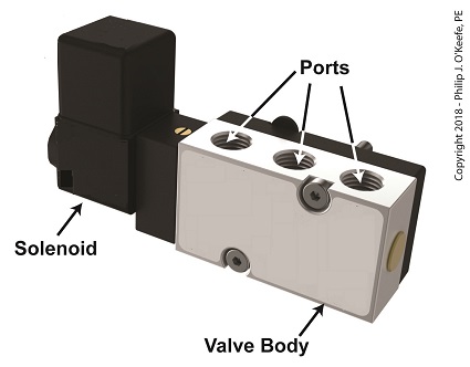
A Solenoid Valve
The solenoid’s plunger is attached to spool in the valve body. The spool is free to move within the valve body past passage ways extending from the ports. In the following illustration, the solenoid valve contains five ports, designated A through E.
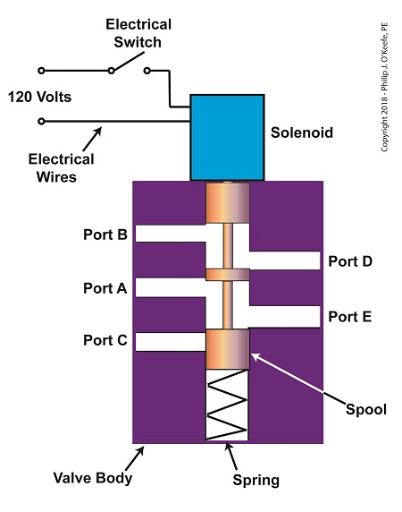
The Solenoid Valve’s Components
Next time we’ll see how the five port solenoid valve operates to create different compressed air flow paths between its ports.
Copyright 2018 – Philip J. O’Keefe, PE
Engineering Expert Witness Blog
____________________________________ |
Tags: coil, compressed air, depositor, engineers, food manufacturing, jelly filling, magnetic field, pastry line, plunger, port, solenoid, solenoid valve, spool, switch, valve body, voltage source
Posted in Engineering and Science, Expert Witness, Forensic Engineering, Innovation and Intellectual Property, Personal Injury, Product Liability, Professional Malpractice | Comments Off on The Solenoid Valve’s Components
Saturday, January 14th, 2012
| When a starving monkey is faced with two buttons, one representing access to a banana, the other cocaine, which will he push? The cocaine, every time. The presence of buttons usually indicates a choice must be made, and electric relays illustrate this dynamic.
Last week we looked at a basic electric relay and saw how it was used to facilitate a choice in electricity flow between two paths in a circuit. Now let’s see what happens when we put a relay to use within a basic industrial control system making use of lit bulbs.

Figure 1
Figure 1 shows an electric relay that’s connected to both hot and neutral wires. At the left side is our pushbutton and the hot wire, on the right two bulbs, one lit, one not, and the neutral wire. No one is depressing the pushbutton, so an air gap exists, preventing current from flowing through the wire coil between the hot and neutral sides. With these conditions in place the relay is said to be in its “normal state.”
The relaxed spring positioned on the relay armature keeps it touching the N.C. contact. This allows current to flow between hot and neutral through the armature and the N.C. contact. When these conditions exist the red bulb is lit, and this is accomplished without the need for anyone to throw a switch or press a button. In this condition the other lamp will remain disengaged and unlit.
Now let’s refer to Figure 2 to see what happens when someone presses the button.

Figure 2
When the button is depressed the air gap is eliminated and the coil and wire become magnetized. They will attract the steel armature closer to them, the spring to expand, and the armature to engage with the N.O. contact. Under these conditions current will no longer flow along a path to light the red bulb because an air gap has been created between the armature and N.C. contact. The current instead flows through the N.O. contact, lighting the green bulb. It will stay lit so long as someone holds the button down.
If our monkey were faced with the scenarios presented in Figures l and 2 and a banana was placed in the position of the red bulb, the cocaine in the position of the green, he might find that the regular delivery of bananas that takes place when the relay is in the N.C. contact position is enough to keep him happy. In this state he might be so full of bananas he won’t want to expend the energy to engage the button into the N.O. contact position for the delivery of cocaine.
Next time we’ll revisit the subject of ladder diagrams and see how they are used to denote the paths of electric relays.
____________________________________________ |
Tags: armature, bulb, coil, electric circuit, electric current, electric relay example, electricity flow, electro-mechanical relay, electromagnet, engineering expert witness, forensic engineer, hot, hot wire, industrial control, lamp, N.C. contact, N.O. contact, NC contact, neutral, neutral wire, NO contact, normal state, normally closed contact, normally open contact, pushbutton, relay, spring, switch, wire coil
Posted in Engineering and Science, Expert Witness, Forensic Engineering, Innovation and Intellectual Property, Personal Injury, Product Liability, Professional Malpractice | 1 Comment »
Monday, January 9th, 2012
| It’s a dark and stormy night and you’ve come to the proverbial fork in the road. The plot is about to take a twist as you’re forced to make a decision in this either/or scenario. As we’ll see in this article, an electric relay operates in much the same manner, although choices will be made in a forced mechanical environment, not a cerebral one.
When we discussed basic electric relays last week we talked about their resting in a so-called “normal state,” so designated by industrial control parlance. It’s the state in which no electric current is flowing through its wire coil, the coil being one of the major devices within a relay assembly. Using Figure 3 of my previous article as a general reference, in this normal state a relaxed spring keeps the armature touching the N.C. switch contact. While in this state, a continuous conductive path is created for electricity through to the N.C. point. It originates from the wire on the left side, which leads to the armature pivot point, travels through the armature and N.C. contact points, and finally dispenses through the wire at the right leading from the N.C. contact.
Now let’s look at an alternate scenario, when current is made to flow through the coil. See Figure l, below.

Figure 1
Figure 1 shows the path of electric current as it flows through the wire coil, causing the coil and the steel core to which it’s attached to become magnetized. This magnetization is strong, attracting the steel armature and pulling it towards the steel core, thus overcoming the spring’s tension and its natural tendency to rest in a tension-free state.
The magnetic attraction causes the armature to rotate about the pivot point until it comes to rest against the N.O. contact, thus creating an electrical path en route to the N.O. wire, on its way to whatever device it’s meant to energize. As long as current flows through the wire coil, its electromagnetic nature will attract the armature to it and contact will be maintained with the N.O. juncture.
When current is made to flow through the wire coil, an air gap is created between the armature and the N.C. contact, and this prevents the flow of electric current through the N.C. contact area. Current is forced to follow the path to the N.O. contact only, effectively cutting off any other choice or fork in the road as to electrical path that may be followed. We can see that the main task of an electric relay is to switch current between two possible paths within a circuit, thereby directing its flow to one or the other.
Next time we’ll examine a simple industrial control system and see how an electric relay can be engaged with the help of a pushbutton.
____________________________________________ |
Tags: armature, coil, control relay, control system, current flow, electric current, electric relay, electrical path, electrical relay, electrical switch, electricity, electromagnetic, engineering expert witness, forensic engineering, industrial control, magnetic attraction, N.C., N.C. contact, N.O., N.O. contact, normal state, normally closed, normally open, pushbutton, relay, relay ladder logic, spring, steel core, switch, switch contact, switching current, wire coil
Posted in Engineering and Science, Expert Witness, Forensic Engineering, Innovation and Intellectual Property, Personal Injury, Product Liability, Professional Malpractice | 1 Comment »


