Posts Tagged ‘compressed air’
Monday, August 6th, 2018
|
Last time, we learned how a solenoid valve operates to create different compressed air flow paths through passageways within its valve body. These different air flow paths are created by opening and closing an electrical switch to de-energize and energize a solenoid mounted on the valve body. Now let’s see how engineers use a solenoid valve in a food manufacturing plant to move a depositor’s pneumatic actuator piston back and forth with compressed air pressure.
Consider the pneumatic actuator on the depositor’s scotch yoke. With the solenoid valve’s electrical switch opened, the valve’s spool is pushed up in the valve body by a spring to create air flow paths between Ports A and E and Ports D and B. If compressed air is fed into Port A and the left side of the pneumatic actuator’s cylinder is connected to Port E, then the air pressure moves the actuator’s piston to the right. But, for the actuator piston to move freely to the right, the right side of the cylinder is connected to Port D on the valve body. As the piston moves to the right, it forces air out of the right side of the cylinder, through Port D, through the valve body, and out through Port B to be vented to the atmosphere.
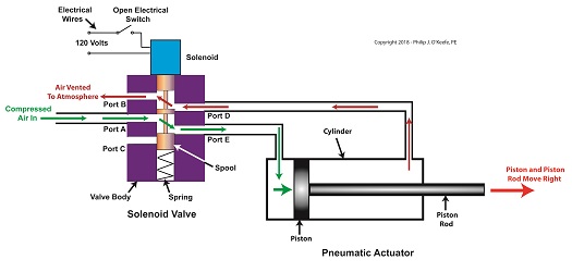
The De-energized Solenoid Valve Operates a Pneumatic Actuator
With the solenoid valve’s electrical switch closed, the spool is pushed down in the valve body by the solenoid, to create air flow paths between Ports A and D and Ports E and C. If compressed air is fed into Port A and the right side of the pneumatic actuator’s cylinder is connected to Port D, then the air pressure moves the actuator’s piston to the left. But, for the actuator piston to move freely to the left, the left side of the cylinder is connected to Port E. As the piston moves left, air is forced out of the left side of the cylinder, through Port E, and vented to the atmosphere through Port C.
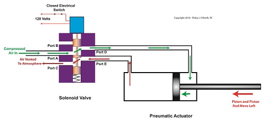
The Energized Solenoid Valve Operates a Pneumatic Actuator
So, in review, opening the solenoid valve’s electrical switch causes the pneumatic actuator piston to move right. Closing the switch causes the piston to move left. But there is a problem with this setup. Operating an electrical switch by hand to deposit jelly filling on thousands of pastries can get tiring after a while. Next time, we’ll see how the valve’s solenoid can be automatically turned on and off by an industrial control system.
Copyright 2018 – Philip J. O’Keefe, PE
Engineering Expert Witness Blog
____________________________________ |
Tags: actuator piston, compressed air, cylinder, depositor, engineers, food manufacturing, pneumatic actuator, ports, Scotch Yoke, solenoid, solenoid valve, spool, valve body
Posted in Engineering and Science, Expert Witness, Forensic Engineering, Innovation and Intellectual Property, Personal Injury, Product Liability | Comments Off on The Solenoid Valve Operates a Pneumatic Actuator
Monday, July 30th, 2018
|
Previously, we looked at the components of a solenoid valve, which is an electro-mechanical device that is commonly used by engineers to operate pneumatic actuators with compressed air. These solenoid valve components include a solenoid and a valve body. We also looked at an illustration of an example solenoid valve. Its valve body had five ports for connections to compressed air pipes. Now, let’s see how the example solenoid valve operates to create different compressed air flow paths between its ports.
When the solenoid valve’s electrical switch is opened, the flow of electrical current from its 120 Volt supply is interrupted. This results in the solenoid’s wire coil being de-energized. As such, the coil generates no magnetic field. Without the magnetic field, there is no downward force exerted on the solenoid’s plunger and the valve body’s spool. A spring at the bottom of the valve body acts upon the spool to force it upward in the valve body and hold it there. With the spool in the upward position, two compressed air flow paths are created in the valve body. One path extends through a passageway connecting Ports D and B, and the other extends through a passageway connecting Ports A and E. The spool seals off the passageway leading to Port C.
The Solenoid Valve’s Operation: De-energized
When the electrical switch is closed, the 120 Volt supply is connected to the valve’s solenoid. This results in the solenoid’s coil becoming energized. When that happens, the electrical current flowing through the coil generates a magnetic field. The magnetic field forces the plunger and spool in the downward direction. The spool overcomes the spring force and moves into a downward position within the valve body. In this position, the spool creates a new pair of compressed air flow paths. These paths remain as long as the current flows through the solenoid’s coil. One compressed air flow path extends between Ports A and D. The other path extends between Ports E and C. The spool seals off the passageway leading to Port B.

The Solenoid Valve’s Operation: Energized
When the electrical switch opens, the solenoid’ coil again becomes de-energized. The magnetic field collapses, and no downward force remains on the plunger and spool. The spring forces the spool back up in the valve body. Once again, a pair of compressed air flow paths is created between Ports D and B, and between Ports A and E. The passageway to Port C is sealed off by the spool.
Next time, we’ll see how the example solenoid valve’s operation is applied to move the piston back and forth in a depositor’s pneumatic actuator.
Copyright 2018 – Philip J. O’Keefe, PE
Engineering Expert Witness Blog
____________________________________ |
Tags: air flow path, compressed air, depositor, engineering, magnetic field, plunger, pneumatic actuator, ports, solenoid, solenoid valve, spool, valve body
Posted in Engineering and Science, Expert Witness, Forensic Engineering, Innovation and Intellectual Property, Personal Injury, Product Liability | Comments Off on The Solenoid Valve’s Operation
Monday, July 23rd, 2018
|
So far in this series of articles, we have talked about pneumatic actuators that move jelly filling through a depositor on a pastry production line in a food manufacturing plant. These actuators have pistons with piston rods that create linear motion. The direction of this motion depends on which side compressed air is admitted to the piston inside the actuator. Now, let’s begin discussing a device known to engineers as a solenoid valve. These valves are used to selectively admit compressed air to either side of the pneumatic actuator’s piston, and thus, change the direction of the actuator’s linear motion.
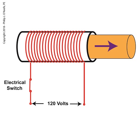
As a solenoid valve’s name implies, a key component is a solenoid. A solenoid consists of a tube, having a coil of wire wrapped around its exterior. Electrical wires extend from the coil to an electrical switch and a voltage supply of, for example, 120 Volts. Inside the tube, there is a steel plunger that is free to move. When the switch is open, the coil is de-energized. That is, no electric current flows from the voltage supply through the coil of wire.
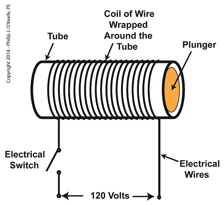
A De-Energized Solenoid
When the electrical switch is closed, the coil becomes energized. As electrical current flows through the coil, a magnetic field is created in the tube. This field forces the steel plunger out of the tube. The magnetic field and force on the plunger remain as long as the switch is closed.
An Energized Solenoid
A solenoid valve consists of a solenoid that is attached to a metal valve body. The solenoid is typically enclosed in a plastic or metal housing. The valve body contains various ports. The ports are threaded holes for the connection of compressed air pipes.
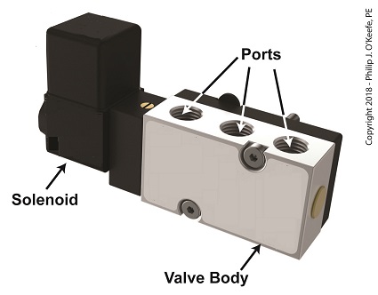
A Solenoid Valve
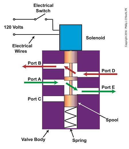
The solenoid’s plunger is attached to spool in the valve body. The spool is free to move within the valve body past passage ways extending from the ports. In the following illustration, the solenoid valve contains five ports, designated A through E.
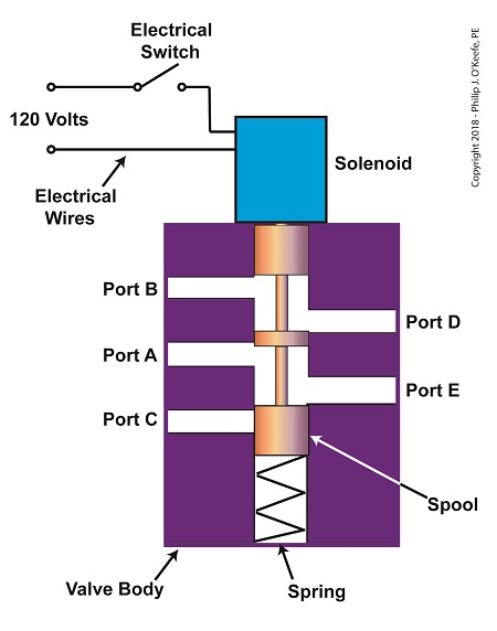
The Solenoid Valve’s Components
Next time we’ll see how the five port solenoid valve operates to create different compressed air flow paths between its ports.
Copyright 2018 – Philip J. O’Keefe, PE
Engineering Expert Witness Blog
____________________________________ |
Tags: coil, compressed air, depositor, engineers, food manufacturing, jelly filling, magnetic field, pastry line, plunger, port, solenoid, solenoid valve, spool, switch, valve body, voltage source
Posted in Engineering and Science, Expert Witness, Forensic Engineering, Innovation and Intellectual Property, Personal Injury, Product Liability, Professional Malpractice | Comments Off on The Solenoid Valve’s Components
Monday, July 2nd, 2018
|
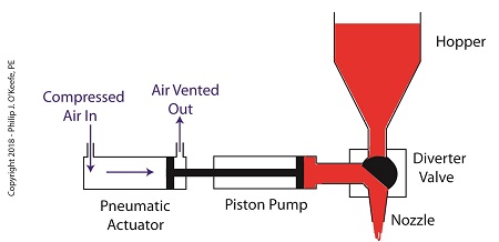
Last time we learned how pneumatic actuators impart linear motion to machines. Now, let’s see how the pneumatic actuator is connected to the depositor’s pump. The connection imparts linear motion to the pump so it draws in jelly filling from the supply hopper and sends it streaming out of the nozzle onto a passing pastry.
On the depositor, the pneumatic actuator’s piston rod is connected to the pump’s piston. As such, the pistons in the actuator and pump move together. When compressed air is admitted to the right side of the pneumatic actuator, the pistons in actuator and pump move to the left. As the pump’s piston moves to the left, a vacuum is formed in the pump. This vacuum sucks the jelly out of the hopper, through the diverter valve, and into the pump as shown below.
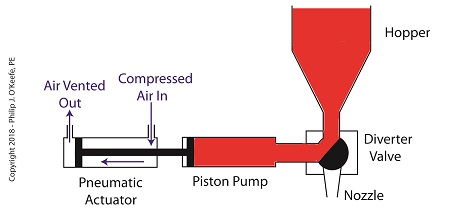
The Depositor’s Pneumatically Actuated Pump
Once the pump is full of jelly, compressed air is admitted to the left side of the actuator piston. The pistons in actuator and pump move to the right as the compressed air expands and presses against the piston in the actuator. As the pump’s piston moves to the right, pressure builds up on the jelly in the pump. The pressure empties the jelly from the pump. The jelly is forced from the pump, back through the diverter valve, and it streams out of the nozzle as shown below.
The Depositor’s Pneumatic Actuator Empties the Pump
For the pumping process to take place, the diverter valve must be rotated to first allow jelly to flow from the hopper. The diverter valve must be rotated again to allow jelly to flow through the nozzle. Next time, we’ll see how a pneumatic actuator is attached to a mechanical linkage that rotates the diverter valve.
Copyright 2018 – Philip J. O’Keefe, PE
Engineering Expert Witness Blog
____________________________________ |
Tags: compressed air, depositor, jelly filling, linear motion, pastry, piston, piston rod, pneumatic actuator, pump, pump vacuum
Posted in Engineering and Science, Expert Witness, Forensic Engineering, Innovation and Intellectual Property, Personal Injury, Product Liability | Comments Off on The Depositor’s Pneumatically Actuated Pump
Thursday, June 21st, 2018
|
Last time we learned that a fruit jelly depositor in a food manufacturing plant is an example of a positive displacement pump at work. Today we’ll see how pieces of equipment on the depositor, known as a pneumatic actuators, work. Pneumatic actuators do not come in contact with the jelly flowing through the depositor. In other words, no jelly flows through the actuators. The jelly only flows through the transfer valve and positive displacement pump as we saw last time. The pump and valve can’t move by themselves. So, they need some device to set them in motion. That’s where the pneumatic actuators come into play. They impart movement to the pump and transfer valve to get the jelly flowing from the hopper and down through the nozzle and onto the pastry.
A pneumatic actuator is a device that operates using compressed air. Compressed air, from an external air compressor, enters into a tube in the actuator known as a cylinder. Inside the cylinder is a piston that can move along the length of the tube. Attached to the piston is a piston rod which extends to the outside of the cylinder.
When compressed air is introduced into the cylinder on the left side of the piston, it forces the piston and piston rod to move towards the right side of the cylinder. But, air must be vented out to atmosphere from the right side of the piston for this movement to occur. If no venting took place, trapped air to the right of the piston will get squeezed between the piston and the right end of the cylinder. When the air gets squeezed, it becomes pressurized. The pressure will impede the movement of the piston.
Likewise, when compressed air is introduced into the cylinder on the right side of the piston, it forces the piston and piston rod to move towards the left side of the cylinder.
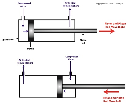
The Depositor’s Pneumatic Actuator
So, depending on which end compressed air is admitted to the pneumatic actuator’s cylinder, the piston rod will move to the left or the right. In engineering terms, the actuator imparts linear motion to machines. In other words, the piston rod moves back and forth in a straight line.
Next time, we’ll see how the pneumatic actuator is connected to the depositor’s pump to impart the linear motion that draws jelly from the supply hopper and sends it streaming out of the nozzle onto a passing pastry.
Copyright 2018 – Philip J. O’Keefe, PE
Engineering Expert Witness Blog
____________________________________ |
Tags: compressed air, compressor, cylinder, depostitor, engineering, food manufacturing, linear motion, piston, piston rod, pneumatic actuator, pump, transfer valve
Posted in Engineering and Science, Expert Witness, Forensic Engineering, Innovation and Intellectual Property, Personal Injury, Product Liability | Comments Off on The Depositor’s Pneumatic Actuator


