Posts Tagged ‘linear motion’

The Depositor’s Scotch Yoke Motion

Monday, July 16th, 2018

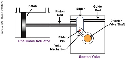
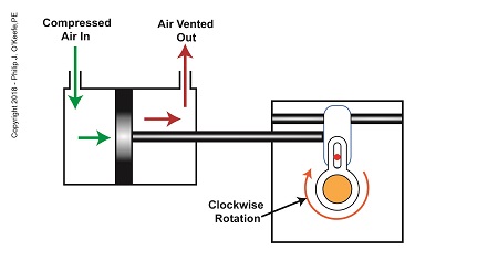
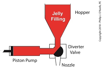
    In my previous article, I introduced a mechanism known to engineers as a Scotch Yoke.   It converts linear motion of a pneumatic actuator into rotary motion.   With regard to the jelly filling depositor on a pastry production line, the Scotch Yoke converts the pneumatic actuator’s linear motion into the rotary motion needed to operate the depositor’s diverter valve.   Now, let’s follow the Scotch Yoke’s motion in this application.

    When the pneumatic actuator’s piston is all the way to the left, the Scotch Yoke’s slider is all the way to the left on the guide rod.   The slider pin is at the top of the slot in the yoke mechanism.   The diverter valve is positioned to create a path for the jelly so it can be emptied from the pump through the nozzle.

 The Depositor’s Scotch Yoke

The Depositor’s Scotch Yoke Slider Is Full Left


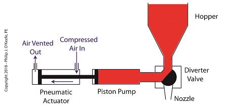
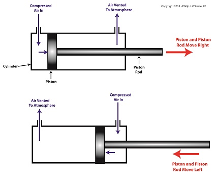
    As compressed air is introduced to the left side of the actuator’s piston, the piston moves to the right, and the slider also moves to the right.   As this happens, the slider pin begins to move in the yoke mechanism’s slot, and the diverter valve shaft begins to rotate clockwise.

The Depositor’s Scotch Yoke Clockwise Rotation

The Depositor’s Scotch Yoke Clockwise Rotation


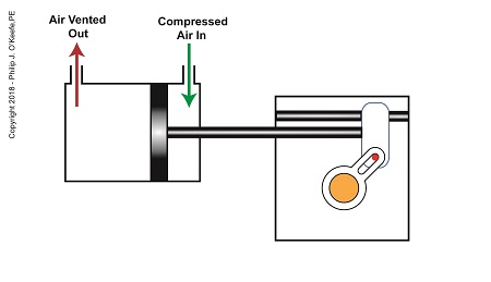
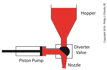
    After the piston moves all the way to the right, and the diverter valve shaft stops its clockwise rotation.   The diverter valve is positioned to create a path between the pump and hopper so the pump can suck in jelly from the hopper.   When the pump is full of jelly, compressed air is introduced to the right side of the piston.

 The Depositor’s Scotch Yoke Slider Is Full Right

The Depositor’s Scotch Yoke Slider Is Full Right


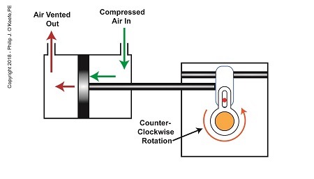
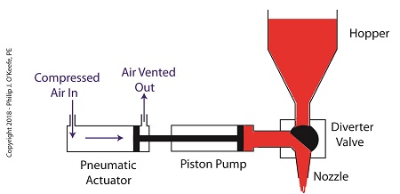
    As compressed air is introduced to the right side of the actuator’s piston, the piston moves to the left, and the Scotch Yoke’s slider also moves to the left.   As this happens, the slider pin begins to move in the yoke mechanism’s slot, and the diverter valve shaft begins to rotate counterclockwise.

 The Depositor’s Scotch Yoke Counterclockwise Rotation

The Depositor’s Scotch Yoke Counterclockwise Rotation


    After the piston moves all the way to the left, the diverter shaft stops its counterclockwise rotation.   The diverter valve is once again positioned to create a path so the jelly can flow from the pump through the nozzle.   After all the jelly is emptied from the pump, compressed air is introduced to the left side of the piston to repeat the previously described motion.

    But what selectively admits compressed air to either the right or left of the pneumatic actuator’s piston?   Next time, we’ll find out when we discuss a device called a solenoid valve.

Copyright 2018 – Philip J. O’Keefe, PE

Engineering Expert Witness Blog

____________________________________


The Depositor’s Scotch Yoke

Monday, July 9th, 2018

    Last time, we learned how a pneumatic actuator was connected to a depositor’s positive displacement piston pump so that it could extract jelly filling from a hopper, and deposit it through a nozzle onto a passing pastry.   The pneumatic actuator imparted linear motion to the pump during this process.   Since the pistons in the actuator and pump both move in a straight line, it was very easy and straightforward to connect the actuator to the pump.

    For the depositing process to work, we must have an additional actuator to rotate the diverter valve as the pump operates.   The valve changes the flow path of the jelly between the hopper and the nozzle.   More specifically, the valve must rotate clockwise to create a flow path between the hopper and the pump while the pump extracts jelly from the hopper.

The Diverter Valve Rotated Clockwise

The Diverter Valve Rotated Clockwise


    When the pump is full of jelly, the diverter valve must rotate counter-clockwise to create a flow path between the pump and the nozzle.   This path allows the pump to empty its contents trough the nozzle.

The Diverter Valve Rotated Counter-Clockwise

The Diverter Valve Rotated Counter-Clockwise


    Although the diverter valve’s motion is rotary, it can be operated with the linear motion of a pneumatic actuator.   To convert the linear motion of the actuator to the rotary motion needed to operate the valve, we can employ a device known to engineers as a Scotch Yoke.

The Depositor’s Scotch Yoke

The Depositor’s Scotch Yoke


    In the Scotch Yoke, the pneumatic actuator’s piston rod is connected to a slider.   As the piston moves back and forth in the pneumatic actuator, the slider is free to move back and forth along a fixed guide rod.   A pin is located on the slider.   The pin loosely engages a slot in the yoke mechanism.   As the slider moves, the pin can move freely in the slot.   The yoke mechanism is rigidly attached to the rotating diverter valve shaft.

    Next time, we’ll look at the rotary motion of the Scotch Yoke as the pneumatic actuator piston moves to the right and then to the left during the jelly depositing process.

Copyright 2018 – Philip J. O’Keefe, PE

Engineering Expert Witness Blog

____________________________________


The Depositor’s Pneumatically Actuated Pump

Monday, July 2nd, 2018

    Last time we learned how pneumatic actuators impart linear motion to machines.   Now, let’s see how the pneumatic actuator is connected to the depositor’s pump.   The connection imparts linear motion to the pump so it draws in jelly filling from the supply hopper and sends it streaming out of the nozzle onto a passing pastry.

    On the depositor, the pneumatic actuator’s piston rod is connected to the pump’s piston.   As such, the pistons in the actuator and pump move together. When compressed air is admitted to the right side of the pneumatic actuator, the pistons in actuator and pump move to the left.   As the pump’s piston moves to the left, a vacuum is formed in the pump.   This vacuum sucks the jelly out of the hopper, through the diverter valve, and into the pump as shown below.

 The Depositor’s Pneumatic Actuator Empties the Pump

The Depositor’s Pneumatically Actuated Pump


    Once the pump is full of jelly, compressed air is admitted to the left side of the actuator piston.   The pistons in actuator and pump move to the right as the compressed air expands and presses against the piston in the actuator.   As the pump’s piston moves to the right, pressure builds up on the jelly in the pump.   The pressure empties the jelly from the pump.   The jelly is forced from the pump, back through the diverter valve, and it streams out of the nozzle as shown below.

 The Depositor’s Pneumatic Actuator Empties the Pump

The Depositor’s Pneumatic Actuator Empties the Pump


    For the pumping process to take place, the diverter valve must be rotated to first allow jelly to flow from the hopper.   The diverter valve must be rotated again to allow jelly to flow through the nozzle.   Next time, we’ll see how a pneumatic actuator is attached to a mechanical linkage that rotates the diverter valve.

Copyright 2018 – Philip J. O’Keefe, PE

Engineering Expert Witness Blog

____________________________________


The Depositor’s Pneumatic Actuator

Thursday, June 21st, 2018

    Last time we learned that a fruit jelly depositor in a food manufacturing plant is an example of a positive displacement pump at work.  Today we’ll see how pieces of equipment on the depositor, known as a pneumatic actuators, work.   Pneumatic actuators do not come in contact with the jelly flowing through the depositor.   In other words, no jelly flows through the actuators.   The jelly only flows through the transfer valve and positive displacement pump as we saw last time.  The pump and valve can’t move by themselves.   So, they need some device to set them in motion.   That’s where the pneumatic actuators come into play.   They impart movement to the pump and transfer valve to get the jelly flowing from the hopper and down through the nozzle and onto the pastry.

    A pneumatic actuator is a device that operates using compressed air.   Compressed air, from an external air compressor, enters into a tube in the actuator known as a cylinder.   Inside the cylinder is a piston that can move along the length of the tube.   Attached to the piston is a piston rod which extends to the outside of the cylinder.

    When compressed air is introduced into the cylinder on the left side of the piston, it forces the piston and piston rod to move towards the right side of the cylinder.   But, air must be vented out to atmosphere from the right side of the piston for this movement to occur.   If no venting took place, trapped air to the right of the piston will get squeezed between the piston and the right end of the cylinder.   When the air gets squeezed, it becomes pressurized.  The pressure will impede the movement of the piston.

    Likewise, when compressed air is introduced into the cylinder on the right side of the piston, it forces the piston and piston rod to move towards the left side of the cylinder.

 The Depositor’s Pneumatic Actuator

The Depositor’s Pneumatic Actuator 


    So, depending on which end compressed air is admitted to the pneumatic actuator’s cylinder, the piston rod will move to the left or the right.   In engineering terms, the actuator imparts linear motion to machines.   In other words, the piston rod moves back and forth in a straight line.

    Next time, we’ll see how the pneumatic actuator is connected to the depositor’s pump to impart the linear motion that draws jelly from the supply hopper and sends it streaming out of the nozzle onto a passing pastry.

Copyright 2018 – Philip J. O’Keefe, PE

Engineering Expert Witness Blog

____________________________________