|
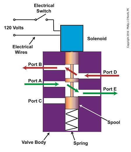
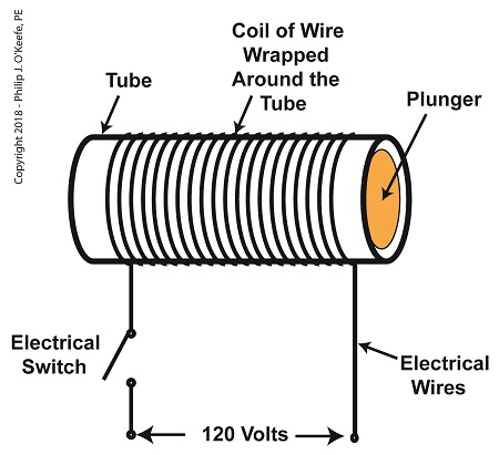
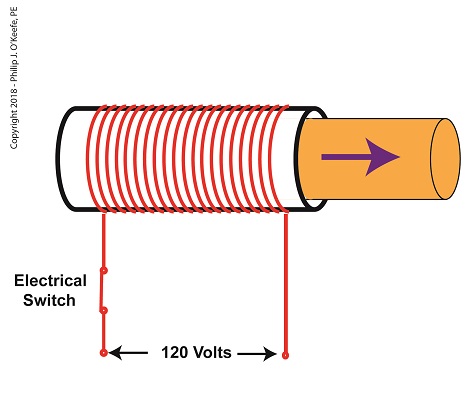
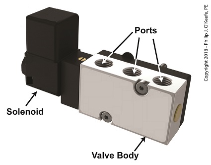
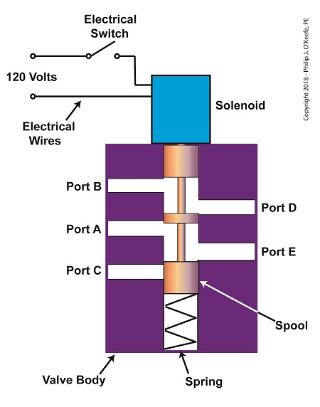
Previously, we looked at the components of a solenoid valve, which is an electro-mechanical device that is commonly used by engineers to operate pneumatic actuators with compressed air. These solenoid valve components include a solenoid and a valve body. We also looked at an illustration of an example solenoid valve. Its valve body had five ports for connections to compressed air pipes. Now, let’s see how the example solenoid valve operates to create different compressed air flow paths between its ports. When the solenoid valve’s electrical switch is opened, the flow of electrical current from its 120 Volt supply is interrupted. This results in the solenoid’s wire coil being de-energized. As such, the coil generates no magnetic field. Without the magnetic field, there is no downward force exerted on the solenoid’s plunger and the valve body’s spool. A spring at the bottom of the valve body acts upon the spool to force it upward in the valve body and hold it there. With the spool in the upward position, two compressed air flow paths are created in the valve body. One path extends through a passageway connecting Ports D and B, and the other extends through a passageway connecting Ports A and E. The spool seals off the passageway leading to Port C. The Solenoid Valve’s Operation: De-energized When the electrical switch is closed, the 120 Volt supply is connected to the valve’s solenoid. This results in the solenoid’s coil becoming energized. When that happens, the electrical current flowing through the coil generates a magnetic field. The magnetic field forces the plunger and spool in the downward direction. The spool overcomes the spring force and moves into a downward position within the valve body. In this position, the spool creates a new pair of compressed air flow paths. These paths remain as long as the current flows through the solenoid’s coil. One compressed air flow path extends between Ports A and D. The other path extends between Ports E and C. The spool seals off the passageway leading to Port B. The Solenoid Valve’s Operation: Energized When the electrical switch opens, the solenoid’ coil again becomes de-energized. The magnetic field collapses, and no downward force remains on the plunger and spool. The spring forces the spool back up in the valve body. Once again, a pair of compressed air flow paths is created between Ports D and B, and between Ports A and E. The passageway to Port C is sealed off by the spool. Next time, we’ll see how the example solenoid valve’s operation is applied to move the piston back and forth in a depositor’s pneumatic actuator.
Copyright 2018 – Philip J. O’Keefe, PE Engineering Expert Witness Blog ____________________________________ |
