| When I think of latches the first thing that comes to mind is my Uncle Jake’s outhouse and how I got stuck in it as a kid. Its door was outfitted with a rusty old latch that had a nasty habit of locking up when someone entered, and it would take a tricky set of raps and bangs to loosen. One day it was being particularly unresponsive to my repeated attempts to open it, and the scene became like something out of a horror movie. There was a lot of screaming.
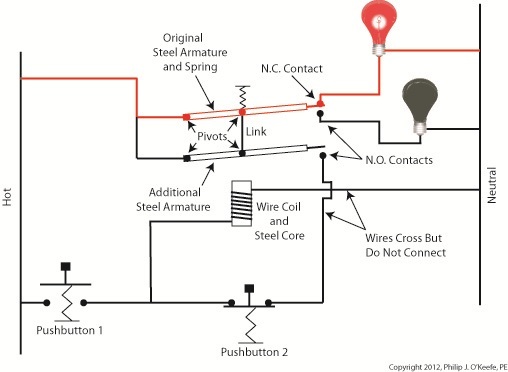
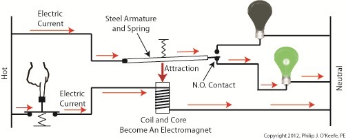
When latches operate well, they’re indispensable. Let’s take our example circuit from last time a bit further by adding more components and wires. We’ll see how a latch can be applied to take the place of pressure exerted by an index finger. See Figure 1. Figure 1
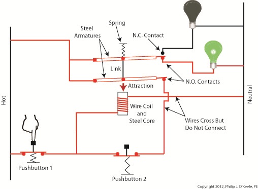
Our relay now contains an additional pivoting steel armature connected by a mechanical link to the original steel armature and spring. The relay still has one N.C. contact, but it now has two N.O. contacts. When the relay is in its normal state the spring holds both armatures away from the N.O. contacts so that no electric current will flow through them. One armature touches the N.C. contact, and this is the point at which current will flow between hot and neutral sides, lighting the red bulb. The parts of the circuit diagram with electric current flowing through them are denoted by red lines. Figure 1 reveals that there are now two pushbuttons instead of one. Now let’s go to Figure 2 to see what happens when someone presses on Button 1. Figure 2
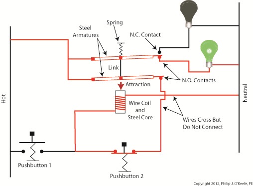
Again, the parts of the circuit diagram with current flowing through them are denoted by red lines. From this diagram you can see that when Button 1 is depressed, current flows through the wire coil, making it and its steel core magnetic. This electromagnet in turn attracts both steel armatures in our relay, causing them to pivot and touch their respective N.O. contacts. Electric current now flows between hot and neutral sides, lighting up the green bulb. Current no longer flows through the N.C. contact and the red bulb, making it go dark. If you look closely at Figure 2, you’ll notice that current can flow to the wire coil along two paths, either that of Button 1 or Button 2. It will also flow through both N.O. contact points, as well as the additional armature. So how is this scenario different from last week’s blog discussion? That becomes evident in Figure 3, when Button 1 is no longer depressed. Figure 3
In Figure 3 Button 1 is not depressed, and electric current does not flow through it. The red bulb remains dark, and the green bulb lit. How can this state exist without the human intervention of a finger depressing the button? Because although one path for current flow was broken by releasing Button 1, the other path through Button 2 remains intact, allowing current to continue to flow through the wire coil. This situation exists because Button 2’s path is “latched.” Latching results in the relay’s wire coil keeping itself energized by maintaining armature contact at the N.O. contact points, even after Button 1 is released. When in the latched state, the magnetic attraction maintained by the wire coil and steel core won’t allow the armature to release from the N.O. contacts. This keeps current flowing through the wire coil and on to the green bulb. Under these conditions the relay will remain latched. But, just like my Uncle’s outhouse door, the relay can be unlatched if you know the trick to it. Relays may be latched or unlatched, and next week we’ll see how Button 2 comes into play to create an unlatched condition in which the green bulb is dark and the red bulb lit. We’ll also see how it is all represented in a ladder diagram. ____________________________________________ |
Posts Tagged ‘electromagnet’
Industrial Control Basics – Introduction to Electric Relays
Tuesday, January 3rd, 2012| I’ve always considered science to be cool. Back in the 5th grade I remember fondly leafing through my science textbook, eagerly anticipating our class performing the experiments, but we never did. For some reason my teacher never took the time to demonstrate any. Undeterred, I proceeded on my own.
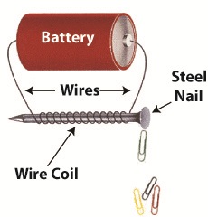
I remember one experiment particularly well where I took a big steel nail and coiled wire around it. When I hooked a battery up to the wires, as shown in Figure 1 below, electric current flowed from the battery through the wire coil. This set up a magnetic field in the steel nail, thereby creating an electromagnet. My electromagnet was strong enough to pick up paper clips, and I took great pleasure in repeatedly picking them up, then watching them unattach and fall quickly away when the wires were disconnected from the battery. Figure 1
Little did I know then that the electromagnet I had created was similar to an important part found within electrical relays used in many industrial control systems. An example of one of these relays is shown in Figure 2. Figure 2
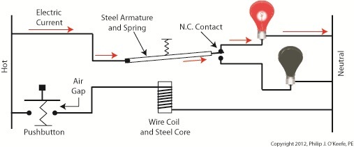
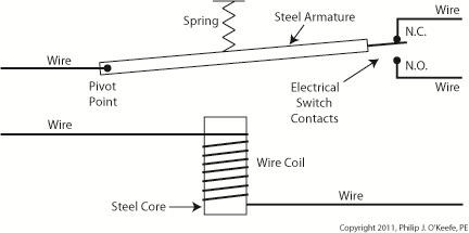
So, what’s in the little plastic cube? Well, a relay is basically an electric switch, similar to the ones we’ve discussed in the past few weeks, the major difference being that it is not operated directly by human hands. Rather, it’s operated by an electromagnet. Let’s see how this works by examining a basic electrical relay, as shown in Figure 3. Figure 3
The diagram in Figure 3 shows a basic electric relay constructed of a steel core with a wire coil wrapped around it, similar to the electromagnet I constructed in my 5th grade experiment. If the coil’s wires are not hooked up to a power source, a battery for example, no electric current will flow through it. When there is no current the coil and steel core are not magnetic. For purposes of our illustration and in accordance with industrial control parlance, this is said to be this relay’s “normal state.” Next to the steel core there is a movable steel armature, a kind of lever, which is attached to a spring. On one end of the armature is a pivot point, on the other end is a set of electrical switch contacts. When the relay is in its normal state, the spring’s tension holds the armature against the “normally closed,” or N.C., contact. If electric current is applied to the wire leading to the pivot point on the armature while in this state, it will be caused to flow on a continuous path through the armature and the N.C. contact, then out through the wire leading from the N.C. contact. In our illustration, since the armature does not touch the N.O. contact, an air gap is created that prevents electric current from traveling through the contact from the armature. Next week we’ll see how these parts come into play within a relay when electric current flows through the coil, turning it into an electromagnet. ____________________________________________ |
