Posts Tagged ‘mechanical advantage’
Saturday, January 7th, 2017
|
Last time we saw how the presence of friction reduces mechanical advantage in an engineering scenario utilizing a compound pulley. We also learned that the actual amount of effort, or force, required to lift an object is a combination of the portion of the force which is hampered by friction and an idealized scenario which is friction-free. Today we’ll begin our exploration into how friction results in reduced work input, manifested as heat energy lost to the environment. The net result is that work input does not equal work output and some of Mr. Toga’s labor is unproductive.
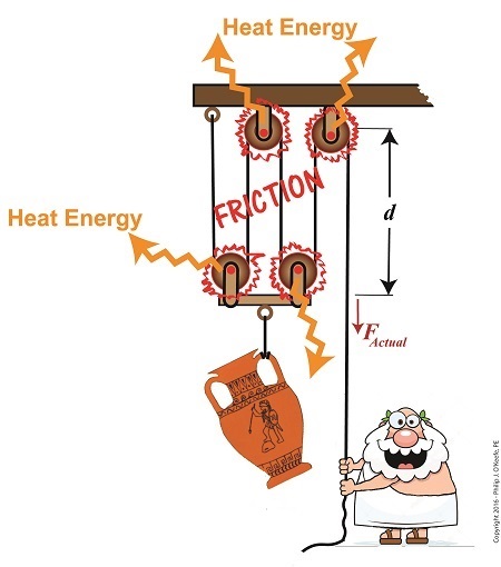
Friction Results in Heat and Lost Work Within a Compound Pulley
In a past blog, we showed how the actual force required to lift our urn is a combination of F, an ideal friction-free work effort by Mr. Toga, and FF , the extra force he must exert to overcome friction present in the wheels,
FActual = F + FF (1)
Mr. Toga is clearly working to lift his turn, and generally speaking his work effort, WI, is defined as the force he employs multiplied by the length, d, of rope that he pulls out of the compound pulley during lifting. Mathematically that is,
WI = FActual × d (2)
To see what happens when friction enters the picture, we’ll first substitute equation (1) into equation (2) to get WI in terms of F and FF,
WI = (F + FF ) × d (3)
Multiplying through by d, equation (3) becomes,
WI = (F × d )+ (FF × d) (4)
In equation (4) WI is divided into two terms. Next time we’ll see how one of these terms is beneficial to our lifting scenario, while the other is not.
Copyright 2017 – Philip J. O’Keefe, PE
Engineering Expert Witness Blog
____________________________________ |
Tags: compound pulley, engineering, friction, heat energy, lost work, mechanical advantage, pulley, reduced work, work input, work output
Posted in Engineering and Science, Expert Witness, Forensic Engineering, Innovation and Intellectual Property, Personal Injury, Product Liability, Professional Malpractice | Comments Off on Friction Results in Heat and Lost Work Within a Compound Pulley
Tuesday, December 13th, 2016
|
The presence of friction in mechanical designs is as guaranteed as conflict in a good movie, and engineers inevitably must deal with the conflicts friction produces within their mechanical designs. But unlike a good movie, where conflict presents a positive, engaging force, friction’s presence in pulleys results only in impediment, wasting energy and reducing mechanical advantage. We’ll investigate the math behind this phenomenon in today’s blog.
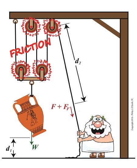
Friction Reduces Pulleys’ Mechanical Advantage
A few blogs back we performed a work input-output analysis of an idealized situation in which no friction is present in a compound pulley. The analysis yielded this equation for mechanical advantage,
MA = d2 ÷ d1 (1)
where d2 is the is the length of rope Mr. Toga extracts from the pulley in order to lift his urn a distance d1 above the ground. Engineers refer to this idealized frictionless scenario as an ideal mechanical advantage, IMA, so equation (1) becomes,
IMA = d2 ÷ d1 (2)
We also learned that in the idealized situation mechanical advantage is the ratio of the urn’s weight force, W, to the force exerted by Mr. Toga, F, as shown in the following equation. See our past blog for a refresher on how this ratio is developed.
IMA = W ÷ F (3)
In reality, friction exists between a pulley’s moving parts, namely, its wheels and the rope threaded through them. In fact, the more pulleys we add, the more friction increases.
The actual amount of lifting force required to lift an object is a combination of FF , the friction-filled force, and F, the idealized friction-free force. The result is FActual as shown here,
FActual = F + FF (4)
The real world scenario in which friction is present is known within the engineering profession as actual mechanical advantage, AMA, which is equal to,
AMA = W ÷ FActual (5)
To see how AMA is affected by friction force FF, let’s substitute equation (4) into equation (5),
AMA = W ÷ (F + FF) (6)
With the presence of FF in equation (6), W gets divided by the sum of F and FF . This results in a smaller number than IMA, which was computed in equation (3). In other words, friction reduces the actual mechanical advantage of the compound pulley.
Next time we’ll see how the presence of FF translates into lost work effort in the compound pulley, thus creating an inequality between the work input, WI and work output WO.
Copyright 2016 – Philip J. O’Keefe, PE
Engineering Expert Witness Blog
____________________________________ |
Tags: actual mechanical advantage, AMA, compound pulley, engineering, friction, friction force, ideal mechanical advantage, IMA, mechanical advantage, mechanical design, pulley, pulley friction, pulley work input, pulley work output, weight force
Posted in Engineering and Science, Expert Witness, Forensic Engineering, Innovation and Intellectual Property, Personal Injury, Product Liability | Comments Off on Friction Reduces Pulleys’ Mechanical Advantage
Wednesday, November 30th, 2016
|
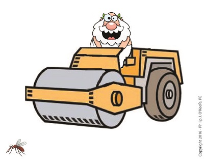
We’ve been discussing the mechanical advantage that compound pulleys provide to humans during lifting operations and last time we hit upon the fact that there comes a point of diminished return, a reality that engineers must negotiate in their mechanical designs. Today we’ll discuss one of the undesirable tradeoffs that results in a diminished return within a compound pulley arrangement when we compute the length of rope the Grecian man we’ve been following must grapple in order to lift his urn. What we’ll discover is a situation of mechanical overkill – like using a steamroller to squash a bug.
Mechanical Overkill
Just how much rope does Mr. Toga need to extract from our working example compound pulley to lift his urn two feet above the ground? To find out we’ll need to revisit the fact that the compound pulley is a work input-output device.
As presented in a past blog, the equations for work input, WI, and work output, WO, we’ll be using are,
WI = F × d2
WO = W × d1
Now, ideally, in a compound pulley no friction exists in the wheels to impede the rope’s movement, and that will be our scenario today. Our next blog will deal with the more complex situation where friction is present. So for our example today, with no friction present, work input equals output…
WI = WO
… and this fact allows us to develop an equation in terms of the rope length/distance factors in our compound pulley assembly, represented by d1 and d2, …
F × d2 = W × d1
d2 ÷ d1 = W ÷ F
Now, from our last blog we know that W divided by F represents the mechanical advantage, MA, to Mr. Toga of using the compound pulley, which was found to be 16, equivalent to the sections of rope directly supporting the urn. We’ll set the distance factors up in relation to MA, and the equation becomes…
d2 ÷ d1 = MA
d2 = MA × d1
d2 = 16 × 2 feet = 32 feet
What we discover is that in order to raise the urn 2 feet, our Grecian friend must manipulate 32 feet of rope – which would only make sense if he were lifting something far heavier than a 40 pound urn.
In reality, WI does not equal WO, due to the inevitable presence of friction. Next time we’ll see how friction affects the mechanical advantage in our compound pulley.
Copyright 2016 – Philip J. O’Keefe, PE
Engineering Expert Witness Blog
____________________________________ |
Tags: compound pulley, engineer, force times distance, lift, mechanical advantage, mechanical design, pulley, rope length, work, work input, work output
Posted in Engineering and Science, Expert Witness, Forensic Engineering, Innovation and Intellectual Property, Personal Injury, Product Liability | Comments Off on Mechanical Overkill, an Undesirable Tradeoff in Compound Pulleys
Friday, November 18th, 2016
|
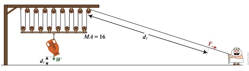
We’re all familiar with the phrase, “too much of a good thing.” As a professional engineer, I’ve often found this to be true. No matter the subject involved, there inevitably comes a point when undesirable tradeoffs occur. We’ll begin our look at this phenomenon in relation to compound pulleys today, and we’ll see how the pulley arrangement we’ve been working with encounters a rope length tradeoff. Today’s arrangement has a lot of pulleys lifting an urn a short distance.
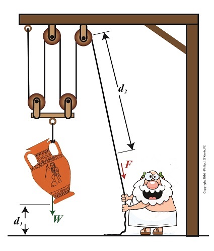
We’ll be working with two distance/length factors and observe what happens when the number of pulleys is increased. Last time we saw how the compound pulley is essentially a work input-output device, which makes use of distance factors. In our example below, the first distance/length factor, d1, pertains to the distance the urn is lifted above the ground. The second factor, d2, pertains to the length of rope Mr. Toga extracts from the pulley while actively lifting. It’s obvious that some tradeoff has occurred just by looking at the two lengths of rope in the image below as compared to last week. What we’ll see down the road is that this also affects mechanical advantage.
The compound pulley here consists of 16 pulleys, therefore it provides a mechanical advantage, MA, of 16. For a refresher on how MA is determined, see our preceding blog.
Rope Length Tradeoff in a Compound Pulley
With an MA of 16 and the urn’s weight, W, at 40 pounds, we compute the force, F, Mr. Toga must exert to actively lift the urn higher must be greater than,
F > W ÷ MA
F > 40 Lbs. ÷ 16
F > 2.5 Lbs.
Although the force required to lift the urn is a small fraction of the urn’s weight, Mr. Toga must work with a long and unwieldy length of rope. How long? We’ll find out next time when we’ll take a closer look at the relationship between d1 and d2.
Copyright 2016 – Philip J. O’Keefe, PE
Engineering Expert Witness Blog
____________________________________ |
Tags: compound pulley, effor, force, mechanical advantage, professional engineer, pulley, rope length, weight force, work
Posted in Courtroom Visual Aids, Engineering and Science, Forensic Engineering, Innovation and Intellectual Property, Personal Injury, Product Liability, Professional Malpractice | Comments Off on Rope Length Tradeoff in a Compound Pulley
Sunday, November 6th, 2016
|
In our last blog we saw how adding extra pulleys resulted in mechanical advantage being doubled, which translates to a 50% decreased lifting effort over a previous scenario. Pulleys are engineering marvels that make our lives easier. Theoretically, the more pulleys you add to a compound pulley arrangement, the greater the mechanical advantage — up to a point. Eventually you’d encounter undesirable tradeoffs. We’ll examine those tradeoffs, but before we do we’ll need to revisit the engineering principle of work and see how it applies to compound pulleys as a work input-output device.
Pulleys as a Work Input-Outut Device
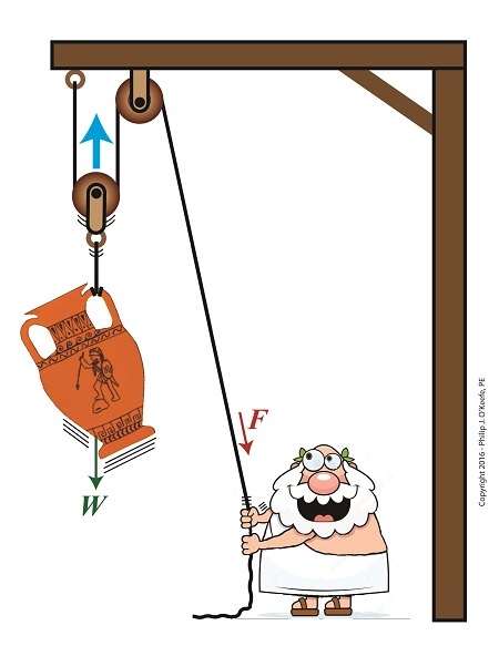
The compound pulley arrangement shown includes distance notations, d1 and d2. Their inclusion allows us to see it as a work input-output device. Work is input by Mr. Toga, we’ll call that WI, when he pulls his end of the rope using his bicep force, F. In response to his efforts, work is output by the compound pulley when the urn’s weight, W, is lifted off the ground against the pull of gravity. We’ll call that work output WO.
In a previous blog we defined work as a factor of force multiplied by distance. Using that notation, when Mr. Toga exerts a force F to pull the rope a distance d2 , his work input is expressed as,
WI = F × d2
When the compound pulley lifts the urn a distance d1 above the ground against gravity, its work output is expressed as,
WO = W × d1
Next time we’ll compare our pulley’s work input to output to develop a relationship between d1 and d2. This relationship will illustrate the first undesirable tradeoff of adding too many pulleys.
Copyright 2016 – Philip J. O’Keefe, PE
Engineering Expert Witness Blog
____________________________________ |
Tags: compound pulley, distance, engineering, engineering principle, force, mechanical advantage, pulley, weight, work, work input-output device, work of lifting
Posted in Engineering and Science, Expert Witness, Forensic Engineering, Innovation and Intellectual Property, Personal Injury, Product Liability | Comments Off on Pulleys as a Work Input-Outut Device
Thursday, October 27th, 2016
|
Last time we saw how compound pulleys within a dynamic lifting scenario result in increased mechanical advantage to the lifter, mechanical advantage being an engineering phenomenon that makes lifting weights easier. Today we’ll see how the mechanical advantage increases when more fixed and movable pulleys are added to the compound pulley arrangement we’ve been working with.
More Pulleys Increase Mechanical Advantage
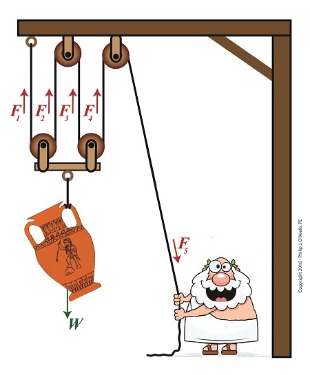
The image shows a more complex compound pulley than the one we previously worked with. To determine the mechanical advantage of this pulley, we need to determine the force, F5, Mr. Toga exerts to hold up the urn.
The urn is directly supported by four equally spaced rope sections with tension forces F1, F2, F3, and F4. The weight of the urn, W, is distributed equally along the rope, and each section bears one quarter of the load. Mathematically this is represented by,
F1 = F2 = F3 = F4 = W ÷ 4
If the urn’s weight wasn’t distributed equally, the bar directly above it would tilt. This tilting would continue until equilibrium was eventually established, at which point all rope sections would equally support the urn’s weight.
Because the urn’s weight is equally distributed along a single rope that’s threaded through the entire pulley arrangement, the rope rule, as I call it, applies. The rule posits that if we know the tension in one section of rope, we know the tension in all rope sections, including the one Mr. Toga is holding onto. Therefore,
F1 = F2 = F3 = F4 = F5 = W ÷ 4
Stated another way, the force, F5 , Mr. Toga must exert to keep the urn suspended is equal to the weight force supported by each section of rope, or one quarter the total weight of the urn, represented by,
F5 = W ÷ 4
If the urn weighs 40 pounds, Mr. Toga need only exert 10 pounds of bicep force to keep it suspended, and today’s compound pulley provides him with a mechanical advantage, MA, of,
MA = W ÷ F5
MA = W ÷ (W ÷ 4)
MA = 4
It’s clear that adding the two extra pulleys results in a greater benefit to the man doing the lifting, decreasing his former weight bearing load by 50%. If we added even more pulleys, we’d continue to increase his mechanical advantage, and he’d be able to lift far heavier loads with a minimal of effort. Is there any end to this mechanical advantage? No, but there are undesirable tradeoffs. We’ll see that next time.
Copyright 2016 – Philip J. O’Keefe, PE
Engineering Expert Witness Blog
____________________________________ |
Tags: compound pulley, engineering, fixed pulley, lifting, mechanical advantage, movable pulley, rope section, tension force
Posted in Engineering and Science, Forensic Engineering, Innovation and Intellectual Property, Personal Injury, Product Liability, Professional Malpractice | Comments Off on More Pulleys Increase Mechanical Advantage
Friday, October 14th, 2016
|
Last time we introduced the engineering concept of mechanical advantage, MA. Thanks to its presence in our compound pulley arrangement, it made a Grecian man’s job of holding an urn suspended in space twice as easy as compared to when he used a mere simple pulley. Today we’ll see what happens when our static scenario becomes active through dynamic lifting and how it affects his efforts.
Dynamic Lifting is Easier With a Compound Pulley
If you’ll recall from our last blog, Mr. Toga used a compound pulley to assist him in holding an urn stationary in space. To do so, he only needed to exert personal bicep force, F, equivalent to half the urn’s weight force, W, which meant he enjoyed a mechanical advantage of 2. Mathematically that is represented by,
F = W ÷ 2
If the urn weighs 40 pounds, then he only needs to exert 20 Lbs of personal effort to keep it suspended.
But when Mr. Toga uses more bicep power with that same compound pulley, he’s able to dynamically raise its position in space until it eventually meets with the beam that supports it. All the while he’ll be exerting a force greater than W ÷ 2. That relationship is represented by,
F > W ÷ 2
In the case of a 40 Lb urn, the lifting force Mr. Toga must exert to dynamically lift the urn is represented by,
F > 40 Lbs ÷ 2
F > 20 Lbs
where F represents a bicep force of at least 20 pounds. Fortunately for him, his efforts will never have to extend much beyond 20 Lbs of effort to lift the urn to the beam. That’s because gravity’s effect will remain nearly constant as the urn climbs, this being due to gravity’s influence upon objects decreasing by an insignificant amount over short distances above the Earth’s surface. As a matter of fact, at an altitude of 3,280 feet, gravity’s pull decreases by a mere 0.2 %.
The net result is that the compound pulley enables the same mechanical advantage whether a static or dynamic scenario exists, that is, regardless of whether Mr. Toga is simply holding the urn stationary in space or he’s actively tugging on his end of the rope to lift it higher.
Next time we’ll see how mechanical advantage increases when we add more fixed and moveable pulleys to our compound pulley arrangement.
Copyright 2016 – Philip J. O’Keefe, PE
Engineering Expert Witness Blog
____________________________________ |
Tags: compound pulley, dynamic lifting, engineering expert, force, gravity, gravity's pull, mechanical advantage, simple pulley, static, weight
Posted in Engineering and Science, Expert Witness, Forensic Engineering, Innovation and Intellectual Property, Personal Injury, Product Liability | Comments Off on Dynamic Lifting is Easier With a Compound Pulley
Thursday, September 29th, 2016
|
In this blog series on pulleys we’ve gone from discussing the simple pulley to the improved simple pulley to an introduction to the complex world of compound pulleys, where we began with a static representation. We’ve used the engineering tool of a free body diagram to help us understand things along the way, and today we’ll introduce another tool to prepare us for our later analysis of dynamic compound pulleys. The tool we’re introducing today is the engineering concept of mechanical advantage, MA, as it applies to a compound pulley scenario.
The term mechanical advantage is used to describe the measure of force amplification achieved when humans use tools such as crowbars, pliers and the like to make the work of prying, lifting, pulling, bending, and cutting things easier. Let’s see how it comes into play in our lifting scenario.
During our previous analysis of the simple pulley, we discovered that in order to keep the urn suspended, Mr. Toga had to employ personal effort, or force, equal to the entire weight of the urn.
F = W (1)
By comparison, our earlier discussion on the static compound pulley revealed that our Grecian friend need only exert an amount of personal force equal to 1/2 the suspended urn’s weight to keep it in its mid-air position. The use of a compound pulley had effectively improved his ability to suspend the urn by a factor of 2. Mathematically, this relationship is demonstrated by,
F = W ÷ 2 (2)
The factor of 2 in equation (2) represents the mechanical advantage Mr. Toga realizes by making use of a compound pulley. It’s the ratio of the urn’s weight force, W, to the employed force, F. This is represented mathematically as,
MA = W ÷ F (3)
Substituting equation (2) into equation (3) we arrive at the mechanical advantage he enjoys by making use of a compound pulley,
MA = W ÷ (W ÷ 2) = 2 (4)
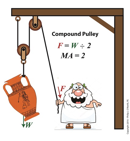
Mechanical Advantage of a Compound Pulley
Next time we’ll apply what we’ve learned about mechanical advantage to a compound pulley used in a dynamic lifting scenario.
Copyright 2016 – Philip J. O’Keefe, PE
Engineering Expert Witness Blog
____________________________________ |
Tags: compound pulley, engineering, force, lifting, mechanical advantage, pulley, simple pulley, static analysis, tools, weight
Posted in Engineering and Science, Expert Witness, Forensic Engineering, Innovation and Intellectual Property, Personal Injury, Product Liability | Comments Off on Mechanical Advantage of a Compound Pulley
Wednesday, April 23rd, 2014
|
Last time we introduced the simplified formula for torque:
Torque = Distance × Force
Today we’ll manipulate it by way of our wrench and nut example to get the torque that we need to loosen a tight nut.

By inserting the numerical values of our illustration into the torque formula, it becomes:
Torque = 6 inches × 10 pounds = 60 inch-pounds
Inch-pounds may be terminology you’re unfamiliar with, but this notation arises from the fact that torque values are always represented by units of distance and force separated by a hyphen, in our case inch-pounds. This just means that distance and force were multiplied together to calculate torque.
In order to manipulate the value for torque all that needs to be done is change either or both numerical values for Distance and Force. Increasing either or both factors produces higher torque, decreasing them less torque. Why manipulate torque? To provide us with a mechanical advantage.
Suppose we have a rusted nut that we’re trying to move with a wrench that has a 6 inch handle, and the 10 pounds of force employed by the muscles in our arm just won’t budge it. Put another way, 60 inch-pounds of torque is insufficient to rotate the nut. It’s clear we must increase torque to get things going. Let’s do so by increasing either of the vector magnitudes.
First we’ll try increasing the magnitude of the force vector. Instead of simply pushing hard on the wrench handle with our arm, let’s say we push extra hard. The average man can do a bicep curl of between 30 to 40 pounds, but we haven’t been going to the gym lately and we’re really out of shape. So try as we will, we just can’t muster up the bicep strength to apply more than 10 pounds of force to the wrench handle. It’s clear that this approach to increasing torque upon the nut isn’t going to work.
The other way to increase torque is to increase the length of the distance vector. We’ll need a wrench with a longer handle, say 9 inches.

By using a wrench with a longer handle we have increased the magnitude of the distance vector from 6 to 9 inches. The torque formula becomes:
Torque = 9 inches × 10 pounds = 90 inch-pounds
Eureka! The longer handle has provided us with the mechanical advantage needed to increase torque to 90 inch-pounds, thereby overcoming our muscular shortcomings and breaking the nut free.
In summary, since torque is the product of the magnitudes of the distance and force vectors, we can increase torque by either increasing the magnitude of the force vector, or as in our example, by increasing the magnitude of the distance vector.
Next time we’ll see how to apply the principles of torque to a real world situation involving gear trains in which we need to obtain a mechanical advantage.
_______________________________________
|
Tags: distance vector, engineering expert witness, force vector, forensic engineer, hand tool expert witness, increase torque, licensed mechanical engineer, mechanical advantage, mechanical engineering expert witness, nut, torque, wrench
Posted in Engineering and Science, Expert Witness, Forensic Engineering, Innovation and Intellectual Property, Personal Injury, Product Liability | Comments Off on Manipulating theTorque Formula
Wednesday, March 19th, 2014
|
Last time we saw how gear train ratios allow us to change the speed of the driven gear relative to the driving gear. Today we’ll extend this concept further and see how gear trains are used to amplify the mechanical power output of small motors and in so doing create a mechanical advantage, an advantage made possible through the physics of torque.
Below is an ordinary electric drill. Let’s see what’s inside its shell.

There’s a whole lot of mechanical advantage at work here, giving the drill’s small motor the ability to perform big jobs. A motor and gear train are housed within the drill itself. The motor shaft is coupled to the chuck shaft via the gear train, and by extension, the drill bit. A chuck holds the drill bit in place.
It’s the drill’s gear train that provides the small motor with the mechanical advantage necessary for this hand-held power tool to perform the big job of cutting through a thick steel plate. If the gear train and its properly engineered gear ratio weren’t in place and the chuck’s shaft was connected directly to the motor shaft, the motor would be overwhelmed and would stall or become damaged. Either way, the work won’t get done.
To understand how operations like these can be performed, we must first familiarize ourselves with the physics concept of torque. Torque allows us to analyze the rotational forces acting upon rotating objects, such as gears in a gear train and wrenches on nuts and bolts. Manipulating torque allows us to achieve a physical advantage when rotating objects around a pivot point. Let’s illustrate this by using a wrench to turn a nut.

The nut is fastened to the bolt with threads, interconnecting spiral grooves formed on both the inside of the nut and the outside of the bolt. A wrench is used to loosen and tighten the nut by rotating it on its mating threads. The nut itself rotates about a pivot point which lies at its center.

When you use your arm to manipulate the wrench you apply force, a force which is transmitted at a distance from the pivot point. This in turn creates a torque on the nut. In other words, torque is a function of the force acting upon the handle relative to its distance from the pivot point at the center of the nut.
Torque can be increased by changing one or both of its acting factors, force and distance. We’ll see how next time when we examine the formula for torque and manipulate it so that a weak arm can loosen even the tightest nut.
_______________________________________
|
Tags: bolt, chuck, distance, drill bit, electric drill, engineering expert witness, force, forensic engineer, gear ratio, gear train, gears, mechanical advantage, mechanical engineer, mechanical engineering expert witness, mechanical fastener expert, motor, nut, physics, pivot point, power tool expert, threads, torque, wrench
Posted in Engineering and Science, Expert Witness, Forensic Engineering, Innovation and Intellectual Property, Personal Injury, Product Liability | Comments Off on Achieving Mechanical Advantage Through Torque


