|
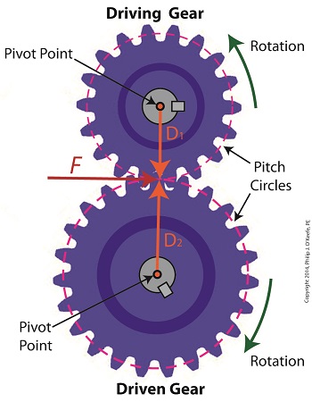
Last time we developed torque equations for the driving and driven gears within a simple gear train. They are, T1 = D1 × F T2 = D2 × F where, T1 and T2 are the driving and driven gear torques, D1 and D2 are the driving and driven gear pitch radii, and F is the resultant Force vector, the common factor between the two equations. Now we’ll combine these two equations relative to F to arrive at a single equation which equates the torques and pitch circle radii of the driving and driven gears in the gear train. This type of computation is commonly used to design gear trains to ensure they perform at a given level. As a first step we’ll use algebra to rearrange terms and place the two equations equal to F. First we’ll do it for the driving gear, dividing both sides of the equation by the pitch circle radius, D1. T1 ÷ D1 = D1 ÷ D1 × F T1 ÷ D1= 1 × F F = T1 ÷ D1 In a similar fashion, we’ll do it for the driven gear by dividing both sides of the equation by the pitch circle radius, D2. T2 = D2 × F → F = T2 ÷ D2 Since F is the common term between the two equations, we can set them up as equal to each other, F = T1 ÷ D1 = T2 ÷ D2 which means that, T1 ÷ D1 = T2 ÷ D2 Next time we’ll see how to use this equation to manipulate our gear train so that it acts as a torque converter by increasing T2 with respect to T1 and the ratio of D1 to D2, thus providing a mechanical advantage to the electric motor the gear train is attached to. _______________________________________ |
Posts Tagged ‘gear design expert’
Equating Torques and Pitch Circle Radii Within a Gear Train
Thursday, May 29th, 2014When Do You Need To Modify Gear Ratio?
Wednesday, February 19th, 2014|
Last time we saw how the involute profile of spur gear teeth ensures smooth contact between gears when they rotate. Today we’ll see why it’s important to be able to change the rotational speed of the driven gear in relation to that of the driving gear by modifying their gear ratio, the speeds at which gears move relative to one another. Why would we want to modify the rotational speeds of gears relative to one another? One reason is to compensate for the fact that alternating electric current (AC) motors drive most modern machinery, and these motors operate at a fixed speed determined by the 60 cycles per second frequency of electricity provided by the utility power grids of North America. By fixed speed I mean that the motor’s shaft revolves at a single, fixed rate. It can’t run any faster or slower. This is fine for some motorized applications, but not others. Basic machinery such as wood cutting saws, grinders, and blowers function well within the parameters of the AC motor’s fixed speed, because their working parts are intended to rotate at the same rate as the motor’s shaft. As a matter of fact, in this instance there’s often no need for a gear train, because the working parts can be connected directly to the motor’s shaft, and the machinery will be powered and function correctly. There are many instances however in which a fixed speed does not match the speed required for more complex machinery to correctly perform precise, specialized tasks. Take a machine tool meant to cut steel bars, for example. It has a rotating part meant to cut through the steel during machining, and to properly do so its cutting tool bit must turn at 400 revolutions per minute (RPM). If it turns any faster, the cut won’t be smooth and the tool bit will overheat and break due to increased friction. If the AC motor driving the machine tool turns at 1750 RPM, a common speed for such motors, then the tool bit will be turning at a much faster rate than the desired 400 RPM, and this presents a problem. To solve the problem we need only add a gear train between the motor and the part containing the tool bit, meaning, we must connect the gear train’s driving gear to the motor’s shaft and a driven gear to the part’s shaft. But in order for this arrangement to work a conversion must take place, that is, we must design the gear train to operate at a specific gear ratio. By gear ratio, I mean the speeds at which the two gears will rotate relative to one another. Next time we’ll introduce the gear ratio formulas that make it all work.
_______________________________________ |


