|
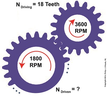
Last time we saw how a gear reduction does as its name implies, reduces the speed of the driven gear with respect to the driving gear within a gear train. Today we’ll see how to work the problem in reverse, so to speak, by determining how many teeth a driven gear must have within a given gear train to operate at a particular desired revolutions per minute (RPM). For our example we’ll use a gear train whose driving gear has 18 teeth. It’s mounted on an alternating current (AC) motor turning at 3600 (RPM). The equipment it’s attached to requires a speed of 1800 RPM to operate correctly. What number of teeth must the driven gear have in order to pull this off? If you’ve identified this to be a word problem, you’re correct. Let’s first review the gear ratio formulas introduced in my previous two articles: R = nDriving ÷ nDriven (1) R = NDriven ÷ NDriving (2) Our word problem provides us with enough information so that we’re able to use Formula (1) to calculate the gear ratio required: R = nDriving ÷ nDriven = 3600 RPM ÷ 1800 RPM = 2 This equation tells us that to reduce the speed of the 3600 RPM motor to the required 1800 RPM, we need a gear train with a gear ratio of 2:1. Stated another way, for every two revolutions of the driving gear, we must have one revolution of the driven gear. Now that we know the required gear ratio, R, we can use Formula (2) to determine how many teeth the driven gear must have to turn at the required 1800 RPM: R = 2 = NDriven ÷ NDriving 2 = NDriven ÷ 18 Teeth NDriven = 2 × 18 Teeth = 36 Teeth The driven gear requires 36 teeth to allow the gear train to operate equipment properly, that is to say, enable the gear train it’s attached to provide a speed reduction of 1800 RPM, down from the 3600 RPM that is being put out from the driving gear. But gear ratio isn’t just about changing speeds of the driven gear relative to the driving gear. Next time we’ll see how it works together with the concept of torque, thus enabling small motors to do big jobs.
_______________________________________ |
Posts Tagged ‘machine part’
Gear Reduction Worked Backwards
Sunday, March 9th, 2014Strength of Materials – Poisson’s Ratio
Sunday, January 16th, 2011| Rubber bands, plastic food wrap, bandages that conform to knuckles and knees, where would we be without them? These are all fairly recent inventions, but their elastic properties were imagined far before they actually came into existence.
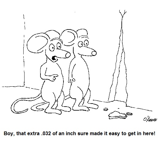
Around the turn of the 19th Century a mathematics genius by the name of Siméon Denis Poisson dabbled in higher level mathematics. He enjoyed working with calculus and probability theories and their applications, and his work eventually led to the discovery of his own special ratio, the “Poisson ratio.” Denoted today by the Greek letter “µ,” his discovery has a great deal to do with elasticity. In fact, much of his work evolved to become the modern study of engineering. If you’ll remember from last week’s blog, we talked about the elasticity of materials, including materials you generally wouldn’t think of as being elastic. In our steel rod example we saw that when you pull on the ends of a steel rod hard enough, you can actually stretch it and make it longer. But where does this extra length come from? According to Poisson’s ratio, as the rod lengthens, its diameter decreases proportionately. The rod’s increased length comes at the expense of its diameter. You can see this effect at work by repeatedly stretching that fat rubber band whose task it is to contain your bulging Sunday paper. The more you pull on it, the skinnier the rubber band becomes. It will eventually get to the point were its elastic properties have been so compromised it won’t even be able to hold together Monday’s paper. Over the decades that have passed since Poisson’s discovery a multitude of laboratory tests have been conducted to determine µ for a vast number of materials. These values have been duly tabulated in engineering reference books, doing away with the tedious task of conducting individualized experimentation by present day design engineers. Steel, for example, has a Poisson’s ratio of around 0.28, and this number is readily available in most strength of materials reference books. It’s pretty obvious why Poisson’s contribution is important to the world of engineering, but now let’s see how his ratio can be applied. Last week we saw that a 15-foot long, 2-inch diameter round steel rod stretches by 0.115 inches when it is pulled by a steady 60,000 pound force. Poisson’s ratio tell us that this results in an accompanying decrease in diameter, but by how much? To find out, we simply multiply the stretched length of the rod by Poisson’s ratio for steel (µ = 0.28). Plugging these numbers into an equation we see that the diameter decreases by: 0.115 inches × 0.28 = 0.032 inches This is approximately the thickness of nine sheets of paper. So if the rod was 2 inches in diameter before the 60,000 pound force was applied, its new diameter after application of the stretching force would be: 2 inches – 0.032 inches = 1.968 inches The change of .032 in the rod’s diameter may not seem like much, but in the world of machine parts it could mean the difference between parts fitting properly or becoming loose. This wraps up our short series on strengths of elastic materials. Next time we’ll move on to discuss coal power plant fundamentals, an arena in which many of the things we’ve been discussing take on real world meaning. _____________________________________________ |


