| Rubber bands, plastic food wrap, bandages that conform to knuckles and knees, where would we be without them? These are all fairly recent inventions, but their elastic properties were imagined far before they actually came into existence.
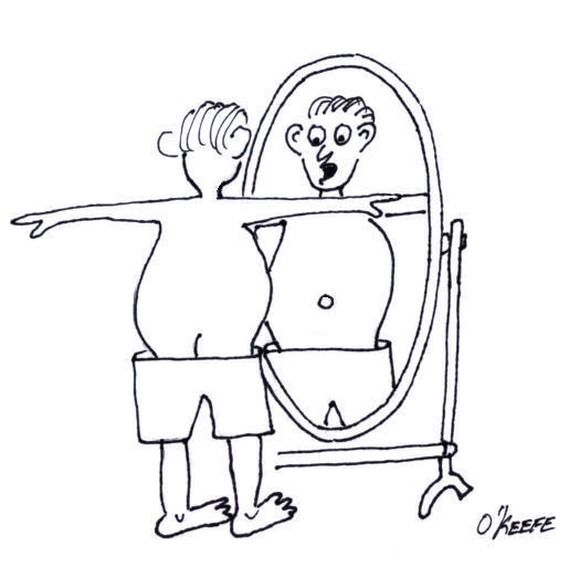
Around the turn of the 19th Century a mathematics genius by the name of Siméon Denis Poisson dabbled in higher level mathematics. He enjoyed working with calculus and probability theories and their applications, and his work eventually led to the discovery of his own special ratio, the “Poisson ratio.” Denoted today by the Greek letter “µ,” his discovery has a great deal to do with elasticity. In fact, much of his work evolved to become the modern study of engineering. If you’ll remember from last week’s blog, we talked about the elasticity of materials, including materials you generally wouldn’t think of as being elastic. In our steel rod example we saw that when you pull on the ends of a steel rod hard enough, you can actually stretch it and make it longer. But where does this extra length come from? According to Poisson’s ratio, as the rod lengthens, its diameter decreases proportionately. The rod’s increased length comes at the expense of its diameter. You can see this effect at work by repeatedly stretching that fat rubber band whose task it is to contain your bulging Sunday paper. The more you pull on it, the skinnier the rubber band becomes. It will eventually get to the point were its elastic properties have been so compromised it won’t even be able to hold together Monday’s paper. Over the decades that have passed since Poisson’s discovery a multitude of laboratory tests have been conducted to determine µ for a vast number of materials. These values have been duly tabulated in engineering reference books, doing away with the tedious task of conducting individualized experimentation by present day design engineers. Steel, for example, has a Poisson’s ratio of around 0.28, and this number is readily available in most strength of materials reference books. It’s pretty obvious why Poisson’s contribution is important to the world of engineering, but now let’s see how his ratio can be applied. Last week we saw that a 15-foot long, 2-inch diameter round steel rod stretches by 0.115 inches when it is pulled by a steady 60,000 pound force. Poisson’s ratio tell us that this results in an accompanying decrease in diameter, but by how much? To find out, we simply multiply the stretched length of the rod by Poisson’s ratio for steel (µ = 0.28). Plugging these numbers into an equation we see that the diameter decreases by: 0.115 inches × 0.28 = 0.032 inches This is approximately the thickness of nine sheets of paper. So if the rod was 2 inches in diameter before the 60,000 pound force was applied, its new diameter after application of the stretching force would be: 2 inches – 0.032 inches = 1.968 inches The change of .032 in the rod’s diameter may not seem like much, but in the world of machine parts it could mean the difference between parts fitting properly or becoming loose. This wraps up our short series on strengths of elastic materials. Next time we’ll move on to discuss coal power plant fundamentals, an arena in which many of the things we’ve been discussing take on real world meaning. _____________________________________________ |
Posts Tagged ‘mechanical failure’
Strength of Materials – Poisson’s Ratio
Sunday, January 16th, 2011Pressurized Containers – ASME Boiler and Pressure Vessel Code
Sunday, October 24th, 2010| Over the last few weeks we looked at the dangers associated with pressurized containers, also known as “pressure vessels.” We also looked at overpressure devices that can keep the pressure from building to the point where the vessel ruptures. But what about keeping pressure vessels from rupturing under normal operating pressure? You know, pressures well below the point where an overpressure device would kick in. This can happen if there is some sort of weakness in the pressure vessel caused by things like poor design, defective materials, or bad welds.
In the 19th Century the machines of the Industrial Revolution were driven by steam. Those magnificent machines advanced our civilization and standard of living. Sounds like a win-win situation, right? Wrong! The downside was that there were no standards for the design of pressure vessels like air storage tanks and boilers. Every engineer had their own ideas as to how they wanted to approach pressure vessel design. I use the word “engineer” loosely because most “engineers” of that time were not college graduates. Some approaches were good, some were bad, and some were in between. The end result was often not good. There were many pressure vessel leaks and explosions that damaged property, caused injury, and took lives. By the turn of the 20th Century industrialization spread far and wide, intensifying safety concerns about pressure vessels. One deadly incident was the straw that broke the camel’s back. On March 10, 1905, the boiler failed in a shoe factory in Brockton, Massachusetts. 58 people were killed and another 117 were injured. The factory was completely destroyed. This tragedy prompted Massachusetts to form a Board of Boiler Rules to write boiler laws. Ohio followed with their own boiler laws. This was a step in the right direction, but each state law was different and a boiler that was legal in one state was illegal in another. There was no standardization between states. In 1911 the American Society of Mechanical Engineers (ASME) formed its Boiler and Pressure Vessel Committee to address the lack of standardization. The committee’s work resulted in publication of the Boiler and Pressure Vessel Code (BPVC). In a nutshell, the BPVC establishes standardized rules governing the design, fabrication, testing, inspection, and repair of boilers and other pressurized vessels and containers. The BPVC set the standards that can be adopted by all states to minimize risk to the public. The ASME is not a government agency, so it cannot enforce compliance with the BPVC. As a matter of fact, compliance with the BPVC by manufacturers has been completely voluntary. However, most state laws now require that pressure vessels must be certified by their manufacturers to be in compliance with the BPVC before they can be sold and put into operation. A certified pressure vessel must be permanently and conspicuously marked with the manufacturer’s name, the date built, serial number, and information about its construction and the type of use it’s designed for. That wraps it up for our series about pressurized containers. Next time, we’ll shift gears and take a look at the project triangle and how it influences the outcome of engineering designs. _____________________________________________ |


