|
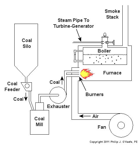
When I was a kid I didn’t have video games or cable TV to help me occupy my time. Back then parents tended to be frugal, and the few games I had were cheap to buy and simple in operation, like the plastic toy windmill I’d play with for hours on end. All I had to do to make it spin was take a deep breath, pucker my lips together, fill my cheeks with breath, then blow hard into the windmill blades. Its spin was fascinating to watch. Little did I know that as an adult I would come to work with a much larger and complex version of it, in the form of a power plant’s steam turbine. You see, when you trap breath within bulging cheeks and then squeeze your cheek muscles together, you actually create a pressurized environment. This air pressure buildup transfers energy from your mouth muscles into the trapped breath within your mouth, so that when you open your lips to release the breath through your puckered lips, the pressurized energy is converted into kinetic energy, a/k/a the energy of movement. The breath molecules flow at high speed from your lips to the toy windmill’s blades, and as they come into contact with the blades their energy is transferred to them, causing the blades to move. A similar process takes place in the coal power plant, where steam from a boiler takes the place of pressurized breath and a steam turbine takes the place of the toy windmill. If you recall from my previous article, the heat energy released by burning coal is transferred to water in the boiler, turning it to steam. This steam leaves the boiler under great pressure, causing it to travel through pipe to the steam turbine, as shown in Figure 1.
Figure 1 – A Basic Steam Turbine and Generator In A Coal Fired Power Plant At its most basic level the inside of a steam turbine looks much like our toy windmill, of course on a much larger scale, and it is very appropriately called a “wheel.” See Figure 2.
Figure 2 – A Very Basic Steam Turbine Wheel The wheel is mounted on a shaft and has numerous blades. It makes use of the pressurized steam that has made its way to it from the boiler. This steam has ultimately passed through a nozzle in the turbine that is directed towards the blades on the wheel. This is the point at which heat energy in the steam is converted into kinetic energy. The steam shoots out of the nozzle at high speed, coming into contact with the blades and transferring energy to them, which causes the turbine shaft to spin. The turbine shaft is connected to a generator, so the generator spins as well. Finally, the spinning generator converts the mechanical energy from the turbine into electrical energy. In actuality, most coal power plant steam turbines have more than one wheel and there are many nozzles. The blades are also more numerous and complex in shape in order to maximize the energy transfer from the steam to the wheels. My Coal Power Plant Fundamentals seminar goes into far greater detail on this and other aspects of steam turbines, but what I have shared with you above will give you a basic understanding of how they operate. So to sum it all up, the steam turbine’s job is to convert the heat energy of steam into mechanical energy capable of spinning the electrical generator. Next time we’ll see how the generator works to complete the last step in the energy conversion process, that is, conversion of mechanical energy into electrical energy. _____________________________________________ |
Posts Tagged ‘steam pipe’


Pressurized Containers – ASME Boiler and Pressure Vessel Code
Sunday, October 24th, 2010| Over the last few weeks we looked at the dangers associated with pressurized containers, also known as “pressure vessels.” We also looked at overpressure devices that can keep the pressure from building to the point where the vessel ruptures. But what about keeping pressure vessels from rupturing under normal operating pressure? You know, pressures well below the point where an overpressure device would kick in. This can happen if there is some sort of weakness in the pressure vessel caused by things like poor design, defective materials, or bad welds.
In the 19th Century the machines of the Industrial Revolution were driven by steam. Those magnificent machines advanced our civilization and standard of living. Sounds like a win-win situation, right? Wrong! The downside was that there were no standards for the design of pressure vessels like air storage tanks and boilers. Every engineer had their own ideas as to how they wanted to approach pressure vessel design. I use the word “engineer” loosely because most “engineers” of that time were not college graduates. Some approaches were good, some were bad, and some were in between. The end result was often not good. There were many pressure vessel leaks and explosions that damaged property, caused injury, and took lives. By the turn of the 20th Century industrialization spread far and wide, intensifying safety concerns about pressure vessels. One deadly incident was the straw that broke the camel’s back. On March 10, 1905, the boiler failed in a shoe factory in Brockton, Massachusetts. 58 people were killed and another 117 were injured. The factory was completely destroyed. This tragedy prompted Massachusetts to form a Board of Boiler Rules to write boiler laws. Ohio followed with their own boiler laws. This was a step in the right direction, but each state law was different and a boiler that was legal in one state was illegal in another. There was no standardization between states. In 1911 the American Society of Mechanical Engineers (ASME) formed its Boiler and Pressure Vessel Committee to address the lack of standardization. The committee’s work resulted in publication of the Boiler and Pressure Vessel Code (BPVC). In a nutshell, the BPVC establishes standardized rules governing the design, fabrication, testing, inspection, and repair of boilers and other pressurized vessels and containers. The BPVC set the standards that can be adopted by all states to minimize risk to the public. The ASME is not a government agency, so it cannot enforce compliance with the BPVC. As a matter of fact, compliance with the BPVC by manufacturers has been completely voluntary. However, most state laws now require that pressure vessels must be certified by their manufacturers to be in compliance with the BPVC before they can be sold and put into operation. A certified pressure vessel must be permanently and conspicuously marked with the manufacturer’s name, the date built, serial number, and information about its construction and the type of use it’s designed for. That wraps it up for our series about pressurized containers. Next time, we’ll shift gears and take a look at the project triangle and how it influences the outcome of engineering designs. _____________________________________________
|

Pressurized Containers – Industrial Overpressure Devices
Sunday, October 17th, 2010| Perhaps you went out on a drive to enjoy a nice summer day. As you ventured into uncharted territory, you might have ended up in an industrial area. There, you noticed factories, chemical plants, and oil refinery complexes, each surrounded by a huge system of pipes and tanks. You might have considered it to be an eyesore, but if you’re an artist and engineer like I am, you might look at it as a form of art, composed of interesting shapes, colors, and patterns. No matter how you look at it, you can bet that there are at least a few pressurized containers in there.
Last time we saw how something as seemingly harmless as a home water heater could become a dangerous missile if the pressure inside builds to the point where the tank ruptures. You can imagine what kind of explosive forces, steam, and chemicals would be unleashed into the surroundings if an industrial sized pressurized container failed due to overpressure. Let’s explore some other types of overpressure devices that are commonly used in industrial settings. One type of overpressure device is a safety valve. They are similar to a water heater relief valve, but they are generally used to relieve overpressure of gases and steam. How do they work? Basically, a safety valve is attached to the top of a pressurized container as shown in the cut away view in Figure 1 below.
Figure 1 – A Basic Safety Valve In The Closed Position A powerful spring in the valve body is designed to force down on the valve and keep it closed if there is normal pressure inside the container. Once the pressure begins to rise to an unsafe level, it pushes up against the valve and overcomes the force of the spring. The valve opens, as shown in Figure 2 below, and the contents of the pressurized container are safely vented out to an area that is normally unoccupied by people. In case you’re wondering, safety valves are commonly used on pressurized storage tanks and boilers.
Figure 2 – A Basic Safety Valve In The Open Position Another way to address the overpressure scenario is to employ a rupture disc. This is in fact a purposely constructed weak spot. It is intentionally built into a pressurized container and is designed so that it will fail when pressure starts to rise. In fact, this disc is designed to fail at a pressure point just below the pressure at which the container itself would fail. The disc is usually located within a vent pipe, which is in turn connected to the container. Should the disc rupture in an overpressure situation, the contents of the pressurized container will safely flow out of the vent pipe to a place normally unoccupied by people. The advantage of using a rupture disc is that they are made to safely release huge quantities of pressurized substances very quickly. The disadvantage in their usage is that they’re a one-time fix. That is, unlike relief or safety valves which may perform their function a multitude of times, a rupture disc is destroyed once it does its job. They are generally used in industrial settings where potential hazards are greater than at home, so once the rupture disc blows, the complete system generally undergoes a shut down so that the disc an be replaced before the pressurized container can be used again. Another option to pressure containment is the use of a fusible plug, usually constructed of a metal that will melt if the temperature within a pressurized container rises above a certain level. The metal plug melts, and excess pressure is vented through the aperture formed into a safe location. These are often used on locomotive boilers and compressed gas cylinders. Like rupture discs, fusible plugs are a one-time fix and must be replaced once they have done their job. Yet another option to pressure containment is to use a temperature limiting control. This category includes devices that monitor temperature and pressure within a pressurized container. If a dangerous situation should develop, the control system reacts, effectively reducing the pressure to prevent failure of the vessel. Automatic combustion control systems for boilers in electric utility power plants use temperature and pressure sensors to keep pressures within safe limits by regulating fuel and air input to the boiler. Next time we’ll cover the American Society of Mechanical Engineers (ASME) Boiler and Pressure Vessel Code (BPVC), which establishes rules governing the design, fabrication, testing, inspection, and repair of boilers and other pressurized containers. _____________________________________________ |


