| Perhaps you went out on a drive to enjoy a nice summer day. As you ventured into uncharted territory, you might have ended up in an industrial area. There, you noticed factories, chemical plants, and oil refinery complexes, each surrounded by a huge system of pipes and tanks. You might have considered it to be an eyesore, but if you’re an artist and engineer like I am, you might look at it as a form of art, composed of interesting shapes, colors, and patterns. No matter how you look at it, you can bet that there are at least a few pressurized containers in there.
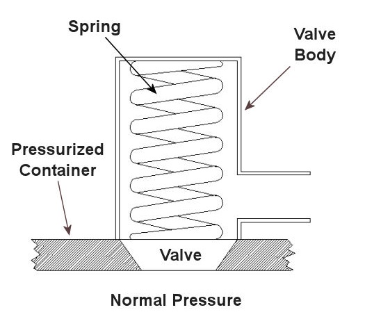
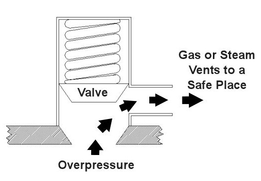
Last time we saw how something as seemingly harmless as a home water heater could become a dangerous missile if the pressure inside builds to the point where the tank ruptures. You can imagine what kind of explosive forces, steam, and chemicals would be unleashed into the surroundings if an industrial sized pressurized container failed due to overpressure. Let’s explore some other types of overpressure devices that are commonly used in industrial settings. One type of overpressure device is a safety valve. They are similar to a water heater relief valve, but they are generally used to relieve overpressure of gases and steam. How do they work? Basically, a safety valve is attached to the top of a pressurized container as shown in the cut away view in Figure 1 below. Figure 1 – A Basic Safety Valve In The Closed Position A powerful spring in the valve body is designed to force down on the valve and keep it closed if there is normal pressure inside the container. Once the pressure begins to rise to an unsafe level, it pushes up against the valve and overcomes the force of the spring. The valve opens, as shown in Figure 2 below, and the contents of the pressurized container are safely vented out to an area that is normally unoccupied by people. In case you’re wondering, safety valves are commonly used on pressurized storage tanks and boilers. Figure 2 – A Basic Safety Valve In The Open Position Another way to address the overpressure scenario is to employ a rupture disc. This is in fact a purposely constructed weak spot. It is intentionally built into a pressurized container and is designed so that it will fail when pressure starts to rise. In fact, this disc is designed to fail at a pressure point just below the pressure at which the container itself would fail. The disc is usually located within a vent pipe, which is in turn connected to the container. Should the disc rupture in an overpressure situation, the contents of the pressurized container will safely flow out of the vent pipe to a place normally unoccupied by people. The advantage of using a rupture disc is that they are made to safely release huge quantities of pressurized substances very quickly. The disadvantage in their usage is that they’re a one-time fix. That is, unlike relief or safety valves which may perform their function a multitude of times, a rupture disc is destroyed once it does its job. They are generally used in industrial settings where potential hazards are greater than at home, so once the rupture disc blows, the complete system generally undergoes a shut down so that the disc an be replaced before the pressurized container can be used again. Another option to pressure containment is the use of a fusible plug, usually constructed of a metal that will melt if the temperature within a pressurized container rises above a certain level. The metal plug melts, and excess pressure is vented through the aperture formed into a safe location. These are often used on locomotive boilers and compressed gas cylinders. Like rupture discs, fusible plugs are a one-time fix and must be replaced once they have done their job. Yet another option to pressure containment is to use a temperature limiting control. This category includes devices that monitor temperature and pressure within a pressurized container. If a dangerous situation should develop, the control system reacts, effectively reducing the pressure to prevent failure of the vessel. Automatic combustion control systems for boilers in electric utility power plants use temperature and pressure sensors to keep pressures within safe limits by regulating fuel and air input to the boiler. Next time we’ll cover the American Society of Mechanical Engineers (ASME) Boiler and Pressure Vessel Code (BPVC), which establishes rules governing the design, fabrication, testing, inspection, and repair of boilers and other pressurized containers. _____________________________________________ |
Posts Tagged ‘overpressure device’
Pressurized Containers – Industrial Overpressure Devices
Sunday, October 17th, 2010Pressurized Containers – Overpressure Devices
Sunday, October 10th, 2010| Have you ever come home to a basement full of water? The sinking feeling in your stomach at the moment of discovery is soon followed by a cascade of other emotions: fear, anger, and you probably had a few choice sailor’s words to round off the experience.
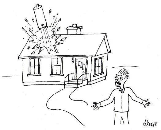
What’s just happened? Well, it may very well have been a water heater explosion, and the water on the floor may be just the beginning of the damage. Perhaps you even have a hole blown into the side of your house! Watch this video for excellent graphic footage of just such an explosion: You probably didn’t realize that the water heater in your home has the potential to become a pressure vessel, and with that present all of the potential dangers that a pressure vessel presents. Remember our discussion on the Boyle-Charles Law a few weeks ago? We learned that in the fixed volume environment of a pressurized container if the temperature keeps climbing, the pressure keeps building, and the outcome of this coupling is precisely what we’re observing in the video. The water in the water heater has turned to steam, causing pressure to build in the vessel until rupture occurs. None of us wants to come home to a basement filled with water, much less a hole blown through our house by a rocketing water heater, so how can we prevent it from happening? One answer is to have your water heater regularly serviced by a qualified plumber. The plumber would make sure that the overpressure device on the water heater tank, namely the relief valve (a.k.a. T&P valve), is in proper working order. Now you may have noticed a circle drawn around the water heater’s relief valve in the video. As their name implies, relief valves are used to relieve pressure buildup, generally of liquids. If the pressure within the water heater reaches a certain limit, set by the heater’s manufacturer, the relief valve will automatically open to vent off the pressure. A pipe on the outlet of the valve safely directs the water and steam that is let off to the floor where it can flow down to a drain. That’s why floor drains are usually located in close proximity to water heaters. Besides relief valves, overpressure devices come in many configurations, including: safety valves, rupture discs, fusible plugs, and temperature limiting controls. They may be used singly or jointly in order to perform the same basic function, that is, to keep the pressure within a vessel from building to the point where it may fail. Next week we’ll explore the other overpressure devices mentioned and where they are generally employed. _____________________________________________ |


