| Ever venture into your basement and stare in amazement at the labyrinth of ductwork stemming off from the furnace? Believe it or not, there’s a science behind that spaghetti bowl configuration. Ductwork can either be flexible or rigid, square or round in shape. Its job in a local exhaust ventilation system is to carry airborne contaminants from the originating source, the carefully positioned hood in the workplace, to the exhaust stack where it is vented outside the building. This job isn’t an easy one. Fluids, like air thick with toxins and toxic gases, don’t want to flow very well through ductwork unless you make their path as unimpeded as possible.
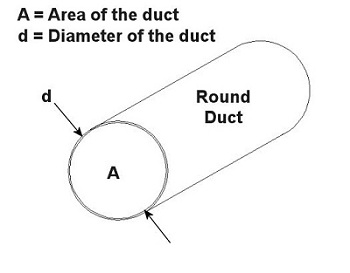
You can think of the air and contaminants flowing through ductwork as if it were like a car moving down a highway. Expressways don’t have sharp 90 degree turns or abrupt changes in width. These would cause a slow down in traffic, unless of course an accident is in the way. Expressways also tend to be rather large thoroughfares. The science behind ductwork follows the same basic principles to work effectively. It will minimize or eliminate sharp turns and it will avoid any abrupt changes in diameter. It will also be as wide in diameter as the environment will accommodate in order to move air volume most effectively. A local exhaust ventilation system’s performance can be greatly hampered and workers exposed to hazards if ductwork leaks. And if the leaks are upstream of the fan and large enough, they can reduce the ability of the local exhaust ventilation system to draw the airborne contaminants into the hood. Air starts getting drawn in through the leaks rather than through the hood. If the leaks are downstream of the fan, the airborne contaminants can re-enter the work area through the leaks rather than going outside through the exhaust stack. Ducts come in an endless variety of diameters, the diameter being part of a simple mathematical equation relating to flow velocity. In the simplest of terms, the flow of air through ductwork is governed by the following equation: Q = V × A where Q is the flow rate of air through the duct in cubic feet per minute (CFM), V is velocity of the air flow in feet per minute, and A is the cross sectional area of the duct in square feet. As an example, suppose you want to design a local exhaust ventilation system with ducts no greater than 5 inches in diameter because of space and clearance limitations. You want to use round ducts for the system because they handle air more efficiently and have no sharp corners where dust can collect. If an industrial hygienist determines that the air is required to flow at a minimum of 800 feet per minute through the duct, what is the airflow rate through the duct? Well, since we are dealing with a round duct, its cross sectional area is that of a circle: A = (π × d2) ÷ 4 where d is the diameter of the inside of the duct as shown in Figure 1 below. Figure 1 – Cross Section of a Round Duct So to use this equation for area, to solve for Q, then we must first convert the duct diameter from inches to feet, which makes our equation look like this: 5 inches ÷ 12 inches per foot = 0.416 feet This gives us a duct cross sectional area of: A = (π × (0.416 feet) 2) ÷ 4 = 0.136 square feet And the air will flow through the duct at this rate: Q = V × A = 800 ft./minute × 0.136 ft.2 = 108.8 CFM This air flow rate is good to know, because it will help the designer to select an appropriate fan for the local exhaust ventilation system. This is because fans are listed in manufacturers’ catalogs according to how many CFM they can handle. Next time, we’ll learn more about the rest of the local exhaust ventilation system, namely, the filter, fan, and exhaust stack. _____________________________________________ |
Posts Tagged ‘fluid mechanics’
Industrial Ventilation – Local Exhaust Ventilation Ductwork
Monday, April 25th, 2011Fluid Mechanics in Mechanical Engineering, Part V, Fluid Dynamics Continued
Sunday, February 7th, 2010|
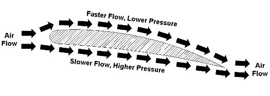
Last week we talked about Daniel Bernoulli and his famous Bernoulli Principle, which is the cornerstone of fluid dynamics. As we’ll see in this week’s installment, the Bernoulli Principle doesn’t just apply to water flowing inside pipes. Let’s consider another instance in which it is instrumental, that of an airplane wing. Figure 1 shows the side view of a wing with arrows indicating direction of air flow as the plane moves through the air. Figure 1 – A Side View of an Airplane Wing
Even though he lived more than 100 years before the first airplane, Bernoulli’s Principle can be used to explain why such a contraption can fly. You see, when comparing air flowing above and beneath a wing, its very shape makes the air flow want to travel faster along the top than it does on the bottom. Bernoulli’s principle comes into play with the airplane wing just as it did in last week’s water pipe flow example. That is, the total energy of flow is the same at all points as the air flows above and below the wing. Now, if air flow speeds up on top of the wing, then the flow’s kinetic energy increases along with it. And remember last week’s analogy of change for $100? Well, something has to give, so in this example the increase in kinetic energy is accomplished at the expense of pressure energy, but the total energy remains the same. This decrease in pressure energy then translates into a drop in pressure on top of the wing. The higher pressure beneath the wing overcomes the lower pressure above the wing. This imbalance is what provides the plane’s lift, enabling it to get off the ground once it achieves a high enough speed on its race down the runway. The Wright brothers, men ahead of their time, were actually among the first aeronautical engineers. They possessed remarkably advanced knowledge of mathematics and mechanical engineering principles. They also understood what Bernoulli taught, and they used his Principle to design and test the shapes of wings on their gliders and planes. They met with success when they determined that the wing’s shape was crucial to supplying lift. In fact, they determined that, depending on the wing’s shape, it would provide the plane with the most lift for the least amount of air speed, allowing them to use a lighter engine to drive the propellers. Weight is always a factor when flying, and the ability to use a lighter engine went a long way towards getting their first plane off the ground. That’s it for Fluid Mechanics. Next week we’ll continue with a discussion of heat transfer, which is the study of how heat moves through vacuums, gases, liquids, and solid objects. _________________________________________________________________ |
Fluid Mechanics in Mechanical Engineering, Part IV, Fluid Dynamics Continued
Sunday, January 31st, 2010|
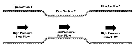
Last week we began our discussion on fluid dynamics. We saw how it’s used to determine flow and velocity of water within a pipe. This week we’ll continue our discussion, exploring in some detail the Bernoulli Principle and what it has to say on the subject. Daniel Bernoulli was a Dutch born mathematician who studied fluid dynamics during the 18th Century. He analyzed the flow of water and determined that as fluid flow speeds up, its pressure goes down, and vice versa. In 1738, he came up with what is now known as the Bernoulli Principle. This Principle is based on the First Law of Thermodynamics, which you will remember teaches us that energy cannot be created or destroyed. One of the conclusions that can be drawn from the Bernoulli Principle is that for fluid flowing steadily, say water within a pipe, or even air flowing over a pitcher’s curve ball in flight, the total energy of the flow remains constant. By “total energy,” I mean the sum of three types of energy: pressure energy, kinetic energy, and potential energy. Total energy will remain constant all along the flow, although its three parts can change. The “pressure energy” part of the total energy is due to the pressure of the fluid flow. For example, pressure energy can be added by a pump to make water flow through a pipe more readily. The “kinetic energy” part of total energy is due to the speed of the fluid flow. And as its name implies, kinetic energy is the energy of movement. The “potential energy” part of the total energy is related to a change in elevation from one end of the fluid flow to the other, like you’d have on a pipe running downhill. It can be said that water at the top of the hill has high potential energy because gravity wants to make it flow down to the bottom of the hill. So how does this Principle help us today? Well, Bernoulli’s Principle is the very foundation upon which fluid dynamics is built, and it’s consistently used to solve complex problems involving fluid flow. To illustrate Bernoulli’s Principle, let’s take a look at Figure l. Here water is flowing through a level pipe with three sections: Figure 1 – Water Flowing Through a Pipe With Three Sections
According to Bernoulli, the total energy of the flowing water is the same from one end of the pipe to the other, and the total energy is equal in each of the three sections of pipe. As the water flows through the pipe from Section 1 to the narrower Section 2, it speeds up as it squeezes through, so its kinetic energy increases. Since the total energy must remain the same and the pipe is level, (this is significant because it means that potential energy is zero), the kinetic energy increases at the expense of pressure energy. This results in a pressure drop in Section 2. Not following? Well, it’s like making change for a hundred dollar bill. Let’s say pressure energy is represented by $20 bills and kinetic energy is represented by $10 bills. Let’s also say that you have $100 worth of these bills in your wallet. The $100 represents the total energy. Now, pretend that you are water flowing into Section 1 of the pipe. While in Section 1, you look in your wallet and you find that you have four $20 bills and two $10 bills, which add up to $100. Okay. Now, when you move into Section 2, you check your wallet again. You discover that your wallet now has three $20 bills and four $10 bills. So you now have fewer $20 bills, more $10 bills, but you still have a total of $100. Fewer $20 bills means lower pressure, and more $10 bills means higher speed. Okay, getting back to the water, what do you think is going to happen when it flows from narrow Section 2 into wide Section 3? Well, the flow will slow down as it fills the extra space present in Section 3. Since the Bernoulli Principle tells us that the total energy of the flow must remain the same, the pressure energy must increase at the expense of the kinetic energy. This in turn causes the pressure within the pipe to go up and the flow’s speed to go down. Thanks to Bernoulli, if we can calculate the total energy in one section of the pipe, then we can calculate the speed of the water flow in another section if the pressure within that section is known. Again, this is possible because we know that the total energy must remain constant all along the flow. Next week we’ll see how the Bernoulli Principle applies to the other type of fluid, air. _________________________________________________________________ |
Fluid Mechanics in Mechanical Engineering, Part III, Fluid Dynamics
Sunday, January 24th, 2010|
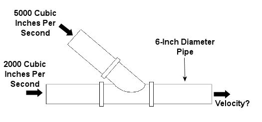
Last week, we learned about some general properties of fluids, concentrating on fluid statics, which is concerned with fluids that don’t move. This week we’ll consider a more dynamic situation, one in which the fluids do move. Remember how we talked about incompressible fluids in the first part of this series on fluid mechanics? We learned that an incompressible fluid, like the oil in a hydraulic jack, can’t be squeezed down into a smaller volume under pressure, so its volume will always remain the same. The same thing goes for other incompressible fluids, like water. By the same token, when water flows through a length of pipe, its volumetric flow rate will remain the same from beginning to end.. By “volumetric flow rate,” I mean the volume of water flowing through the pipe in a given amount of time. It’s measured in cubic inches per second (in3/sec). Now let’s revisit our discussion on the stoichiometry segment of our series on thermodynamics. It’s there that we learned that mass cannot be created or destroyed, and this concept is known as the “conservation of mass.” Applying this principle to incompressible fluids with mass, like water, we can essentially expand on that to say that volume, like mass, can’t be created or destroyed. Because of this, the volumetric flow rate entering the pipe has to equal the flow rate exiting, regardless of whether the pipe diameter changes and whether there are multiple inlets and outlets on the pipe. This volumetric flow rate is related to the velocity, or speed, of water flowing through a round pipe, as well as the interior diameter of the pipe, and it is calculated by this equation: Volumetric Flow Rate = V = (v) x (πd2/4) where “V” is the velocity of the water flowing through the pipe and “d” is the inside diameter of the pipe. The “πd2/4” part of the equation is the cross sectional area of the round pipe. This is derived from the formula used to measure the area of a circle, where the circle’s diameter is “d.” The volumetric flow rate equation above is very useful for designing piping systems used to move of fluids like water from one place to the other. For example, the equation can be used to design the piping system of a municipal water treatment plant. Waste water in, clean water out. Now let’s look at an example. Let’s consider water flowing into the pipe shown in Figure 1 below. If we know the volumetric flow rates of the water going into the two branches, then what would be the velocity of the water coming out?
Figure 1 – A Pipe With Water Flowing Through It
For this problem, let’s use the concept of conservation of volume discussed above and combine it with our volumetric flow rate equation. Applying algebra, we can use the information we are given in Figure 1 to find the solution: Volumetric Flow Rate Going In = Volumetric Flow Rate Going Out VGoing In = VGoing Out VGoing In = [(v) x (πd2/4)]Going Out (VGoing In) / (πd2/4) = vGoing Out vGoing Out = (5000 in3/sec + 2000 in3/sec) / ((π) x (6 in)2/4) = 247.6 in/sec So the water would come shooting out of the pipe at a speed of 247.6 inches per second. That’s pretty fast! Next week we’ll continue with our series on fluid mechanics and explore the Bernoulli principle. By doing so, we’ll examine what’s behind the function of airplane wings and how they enable planes to fly. _________________________________________________________________ |
Fluid Mechanics in Mechanical Engineering, Part II, Fluid Statics Continued
Sunday, January 17th, 2010|
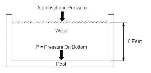
Last week we talked about basic concepts of fluid statics, using the example of a hydraulic jack. This week we’ll continue talking about fluid statics and explore another example. Let’s say you have a 10 foot deep swimming pool and you want to know what the water pressure is at its bottom. Your common sense may tell you that that pressure can be measured by examining the weight of the water itself, and you would be partially correct. But there is another factor that you may not have considered to be significant to the calculation. At this point let me pose a question. How do we breathe? Your answer is directly related to measuring that pressure at the bottom of the pool. You see, contrary to popular belief, air is not weightless, and because it has weight it impacts objects, creating an external pressure. This pressure is known as atmospheric, or barometric, pressure. When you breathe, your diaphragm, which is moved by a muscle, allows the lung cavities to expand or contract accordingly. When the diaphragm is lowered the lung cavities are increased in volume, allowing the atmospheric pressure of your surroundings to come rushing in to fill the space that has been created. Along those lines, it was discovered some time ago that in order to determine the pressure at a given point within a body of water, we must consider not only the depth of the water itself, but also the atmosphere that is above it, bearing down on it. This is illustrated in Figure 1.
Figure 1 – A Swimming Pool Filled With Water
In equation form, this relationship looks like this: P = (Atmospheric Pressure) + (The Specific Weight of Water) x (The Depth of the Water) Now, it’s known that atmospheric pressure at sea level is about 14.7 pounds per square inch. So let’s say that this is the pressure being exerted on the surface of the water in our example by the weight of the air above it. As for the second component of our equation, the water, its specific weight is held to be a constant of approximately 0.036 pounds force per cubic inch. Now there is only one thing left to do before solving our equation, and that is to convert the water’s depth from feet into inches. This must be done so that the units of depth (inches) match the units of specific weight (pounds force per cubic inch) in our calculation. The depth of the water would therefore be 10 feet times 12 inches per foot, or 120 inches. Now we can return to our equation, insert these values, and solve for the pressure at the bottom of the pool: P = 14.7 lbf/in2 + (0.036 lbf/in3) x (120 in) = 19.02 lbf/in2 = 19.02 psi, where “psi” is an abbreviation for pounds per square inch. Notice how the pressure at the bottom of the pool doesn’t depend on how wide or long the pool is? It only depends on its depth. This means the deeper into a body of water that you go, the more water weight will be bearing down upon you, that is to say, the water pressure increases. This is why submarine hulls have a propensity to collapse if they dive too deep. The pressure from the water above gets to be too great compared to the air pressure inside the submarine, and the metal of its hull stresses to the breaking point. It’s like squeezing an egg in your hand. This wraps things up for the topic of fluid statics. Next week we’ll continue with our fluid mechanics series and talk about fluid dynamics. This area of fluid mechanics involves fluids that move, like water moving through pipes and air flowing over airplane wings. _________________________________________________________________ |
Fluid Mechanics in Mechanical Engineering, Part I, Fluid Statics
Sunday, January 10th, 2010|
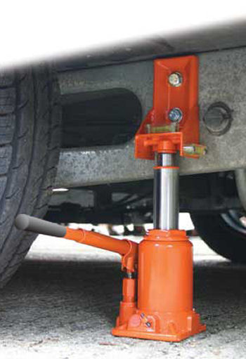
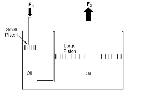
Last week we talked about psychrometry, which involves the analysis of gas and vapor mixtures like air and water. This week we’ll begin our discussion of fluid mechanics, which is the study of the force, pressure, and energy on both stationary and moving fluids. We’ll focus on stationary fluids this week. Let’s clear one thing up before we go any further. By “fluid,” I mean a substance that deforms continuously under a shearing stress, no matter how small. That means that when you try to cut it with a knife, a fluid just gives way under the knife and comes back together again after the knife passes through it. Remember the T-1000 liquid metal man in the movie Terminator II? Now that’s what I’m talking about! Now we all know that liquids are fluids, but did you know that gases are, too? An important concept in fluid mechanics is that liquids, like water and oil, cannot be compressed much when you push down on them in an enclosed container. This is because the molecules of liquids are tightly packed together and they can’t squeeze together any tighter. So, liquids are considered to be incompressible fluids. On the other hand, when you push down on a gas, take air for example, you can compress it within the container. This is because the gas molecules are far apart from each other, so there is plenty of room for them to come closer together. Since there is so much room between their molecules, gases are considered to be compressible fluids. Let’s begin our exploration of fluid mechanics by examining fluids that don’t move, meaning they are static. This field is also known as the study of fluid statics, otherwise known as hydrostatics. We’ll talk about fluids that move, that is, fluid dynamics, later in our series. To show how fluid statics works, suppose you have a hydraulic bottle jack in your garage like the one in Figure 1. When you push down on the lever, it doesn’t take a whole lot of muscle to lift something heavy like a car. Why is that? Let’s see how the jack works by looking at a cutaway diagram. See Figure 2.
Figure 1 – A Hydraulic Bottle Jack Used To Lift A Car
Figure 2 – Inside a Hydraulic Bottle Jack
The jack basically consists of two cylinders, one small, one large. The two cylinders are each filled with oil, and there is a passage between them. Inside each cylinder is a piston. The oil in the jack is a liquid, so it’s incompressible. When you push down on the jack’s lever, you create a force, F1, on the small piston. This then creates equal pressure in the oil under both the small and large pistons. Why? Because the liquid molecules are so tightly packed together, they push against each other and pressure is transmitted equally on all surfaces inside the jack. Now “pressure” is simply a force divided by a unit of area, for example, pounds of force per square inch. In our example it’s the large piston that’s going to lift the weight of the car. Because the large piston has a much larger surface area than the small piston, the fluid in the large cylinder will create a much larger force, F2, to bear up against the car’s weight, thereby lifting it off the ground. Now suppose the small piston has a surface area of 2 square inches, the large piston has a surface area of 20 square inches, and F1 is equal to 50 pounds of force. Since the oil pressure is equal under both pistons as stated above, we can write the flowing equation: Oil Pressure in the Small Piston = Oil Pressure in the Large Piston Once again, pressure is force divided by area, so for our hydraulic jack we can rewrite the equation as follows: (F1)/(Area of the Small Piston) = (F2)/(Area of the Large Piston) Okay, we’re in good shape here, because we know three things: F1, the area of the small piston, and the area of the large piston. So, by plugging this information into the equation, we can use algebra to solve for the upward force, F2, required to lift the car: (50lbf)/(2in2) = (F2)/(20in2) F2 = [(50lbf)/(2in2)] x (20in2) F2 = 500lbf = 500 Pounds of Force So what’s happened here? Well, like magic, the jack uses fluid statics to multiply the input force by a factor of ten. When you push down on the jack handle with 50 pounds of force, you actually produce 500 pounds of force, enough to lift the car. If you made the large piston wider, then its area would be much greater still. For example, if we doubled the size of the large piston from 20 square inches to 40 square inches, F2 would be doubled, so you’d end up with 1000 pounds of force, more than enough to lift an oversized vehicle, like an SUV. Miraculously, the force used to push down on the small piston would remain the same, so there’s no need to worry if you’re a 100-pound weakling. Next week we’ll continue with Part II of our discussion of Fluid Mechanics and talk further about fluid statics.
_________________________________________________________________
|
