|
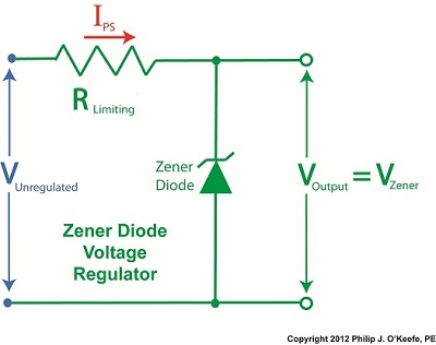
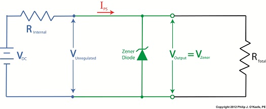
We’ve been discussing the Zener diode voltage regulator circuit, its advantages and disadvantages. We learned that the limiting resistor, RLimiting, creates a major disadvantage in the operation of the circuit, effectively acting as a roadblock to restrict current flow. Let’s see how to improve on that.
Figure 1 illustrates a transistor series voltage regulator circuit.

Figure 1
In this circuit the transistor is known as a bipolar transistor. Like the FET we discussed earlier, it has three electrical connections, however on the bipolar transistor the connections are referred to as the collector, base, and emitter. These are labeled C, B, and E in Figure 1.
The bipolar transistor acts as a valve, resting within the main path of current flow. That is, it controls the flow of electric current traveling from the collector to the emitter, as well as the voltage available at the emitter. The transistor is designed so that current flows in one direction only, from collector to emitter. We’ll talk more about that in our next article.
The limiting resistor, RLimiting, is located on a branch of the circuit leading to the Zener diode and the transistor base. Next time we’ll connect an unregulated power supply and external supply circuit to our transistor series voltage regulator. This will enable us to see how placing RLimiting on the branch, rather than along the main current path, results in a major advantage over using the Zener diode voltage regulator alone.
____________________________________________ |
Tags: base, bipolar transistor, circuit, collector, current flow, electric current, emitter, emitter voltage, engineering expert witness, FET, field effect transistor, forensic engineer, limiting resistor, power supply, regulated power supply, transistor series voltage regulator, transistors, voltage regulation, Zener diode
This entry was posted
on Monday, November 5th, 2012 at 2:19 pm and is filed under Engineering and Science, Expert Witness, Forensic Engineering, Innovation and Intellectual Property, Personal Injury, Product Liability.
You can follow any responses to this entry through the RSS 2.0 feed.
Both comments and pings are currently closed.
 Engineering Expert Witness Blog


