| When my daughter was seven she found out about Ohm’s Law the hard way, although she didn’t know it. She had accidentally bumped into her electric toy train, causing its metal wheels to derail and fall askew of the metal track. This created a short circuit, causing current to flow in an undesirable direction, that is, through the derailed wheels rather than along the track to the electric motor in the locomotive as it should.
What happened during the short circuit is that the bulk of the current began to follow through the path of least resistance, that of the derailed wheels, rather than the higher resistance of the electric motor. Electric current, always opportunistic, will flow along its easiest course, in this case the short, thick metal of the wheels, rather than work its way along the many feet of thin metal wire of the motor’s electromagnetic coils. With its wheels sparking at the site of derailment the train had become an electric toaster within seconds, and the carpet beneath the track began to burn. Needless to say, mom wasn’t very happy. In this instance Ohm’s Law was at work, with a decidedly negative outcome. The Law’s basic formula concerning the toy train would be written as: I = V ÷ Rwhere, I is the current flowing through the metal track, V is the track voltage, and R is the internal resistance of the metal track and locomotive motor, or in the case of a derailment, the metal track and the derailed wheel. So, according to the formula, for a given voltage V, when the R got really small due to the derailment, I got really big. But enough about toy trains. Let’s see how Ohm’s Law applies to an unregulated power supply circuit. We’ll start with a schematic of the power supply in isolation.
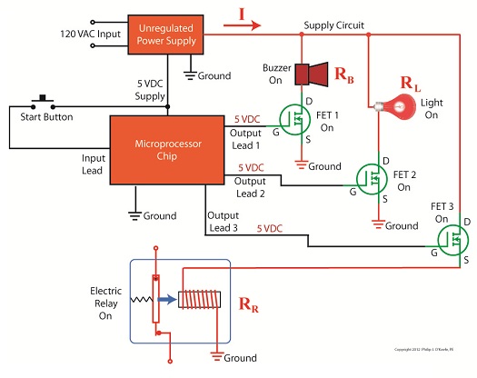
Figure 1The unregulated power supply shown in Figure 1 has two basic aspects to its operation, contained within a blue dashed line. The dashed line is for the sake of clarity when we connect the power supply up to an external circuit which powers peripheral devices later on. The first aspect of the power supply is a direct current (DC) voltage source, which we’ll call VDC. It’s represented by a series of parallel lines of alternating lengths, a common representation within electrical engineering. And like all electrical components, the power supply has an internal resistance, such as discussed previously. This resistance, notated RInternal, is the second aspect of the power supply, represented by another standard symbol, that of a zigzag line. Finally, the unregulated power supply has two output terminals. These will connect to an external supply circuit through which power will be provided to peripheral devices. Next time we’ll connect to this external circuit, which for our purposes will consist of an electric relay, buzzer, and light to see how it all works in accordance with Ohm’s Law. ____________________________________________ |
Posts Tagged ‘volts’

Transformers – The Voltage/Current Trade-Off
Sunday, December 26th, 2010|
As a child I considered the reindeer Rudolph, with his nose so bright, to be a marvel of engineering. Now an adult, I remain perplexed as to the mystery behind the self-generating power source behind his nose. Did it ever overheat? I wondered. Perhaps today’s discussion can shed some light on the matter. During the course of our discussion of electricity certain terms have been tossed about, like voltage and current. For some the distinction between the two may be unclear, and that is what we’ll be addressing today. Electricity is a rather abstract phenomenon, but you may consider the flow of electrical current through a wire to be much like water flowing through a garden hose. The water won’t flow unless there’s sufficient pressure behind it, and that pressure is supplied by pumps, either at your city water works or your personal well. Take away the pressure, and the water stops flowing through the hose. Electricity flows in much the same manner. It requires a pushing pressure to get it on its journey from power plant to home, and that pressure is voltage. Take away voltage, and the current stops flowing through the wire. Voltage is, of course, produced by an electrical generator at the power plant. Last time we saw how an electrical transformer can reduce high voltage to low voltage and how this process also works in reverse. But how can that be? How can low voltage be turned into high? Is it really possible to get “something from nothing”? Let’s take a closer look. When a light bulb burns out in your home, you routinely look at the bulb to see how many watts it is so you can replace it with the same type. But what exactly is a “watt”? It’s a unit of power, and the markings on the bulb tell you how much electrical power it consumes when you use it. Generally speaking, this electrical power is related to voltage and current by this formula: Power = Volts × Electrical Current Knowing this, if I have a 60 watt bulb in a table lamp, and I plug it into a 120 volt wall outlet, then how much electrical current is the lamp going to draw from the outlet? Using the formula above and a little algebra, we get: Electrical Current = Power ÷ Volts Electrical Current = 60 watts ÷ 120 volts = 0.5 amperes And believe it or not, this same formula that’s used to assess power of a light bulb also applies to electrical transformers. Basically, the power going into the transformer is equal to the power coming out. To see how this works, consider the example step-up transformer shown in Figure 1, which converts a low voltage to a higher one. By the way, “step up” transformers have all sorts of applications. For example, they are used by electric utilities to raise the voltage produced by a power plant to make it more economical to transmit to far away customers. We’ll get into that in another article.
Figure 1 – A Step-Up Transformer In this example the input voltage on the primary coil is stepped up from 120 volts to 480 volts on the secondary coil, and this works according to the formula we learned about in last week’s blog: NP ÷ NS = VP ÷ VS where NP and NS are the number of turns of wire in the primary and secondary coils respectively, and VP and VS are the voltages of the primary and secondary coils respectively. Plugging in the numbers we get: 50 turns ÷ 200 turns = 120 volts ÷ VS [(200 turns ÷ 50 turns) × 120 volts] = VS = 480 volts Okay, for the sake of our example let’s say that an electric motor is connected to the 480 volt secondary coil. We have an electric meter hooked up to the primary coil and we measure a 2 ampere (a.k.a. “amps”) electrical current flowing through it. Without having the benefit of another electric meter positioned at the secondary coil, how can we measure how much electrical current is flowing through it? The current flowing through the secondary coil is found by equalizing the power in the primary and secondary coils: PowerP = PowerS Another way of stating this is to say that electrical power is equal to volts times current, so the equation becomes: VP × IP = VS × IS where IP and IS are the primary coil and secondary coil currents, respectively. Plugging in the numbers and working a little algebra we get the electrical current in the secondary coil: 120 volts × 2 amps = 480 volts × IS IS = (120 volts × 2 amps) ÷ 480 volts = 0.5 amps This shows us that the current flowing in the secondary coil is lower than that of the primary coil. It is therefore obvious that the voltage increase in the secondary coil comes at the expense of electrical current that can flow through the secondary coil. Squeeze down on current, voltage goes up. Squeeze down on voltage, current goes up. The power flowing through the transformer stays the same. Conversely, step-down transformers reduce the voltage coming in, and thereby produce the reverse effect. There is an actual increase in current that can flow through the secondary coil. This principle exemplifies the tradeoff process which is often present in science and engineering. Next time we’ll explore how both step-up and step-down transformers are used by electric utilities to transmit power from power plants to its customers tied into the utility grid. As for Rudolph and his power source, that’s still under investigation. _____________________________________________
|


