|
As we’ve come to know through this series of blogs, all electronic components pose some degree of internal resistance to the electric current flowing through them. This resistance results in electrical energy being converted into heat energy, heat which poses potential problems to sensitive components like electronic circuit boards. If things get hot enough, components fail and fires may ignite. To address these issues engineers design circuits with resistors whose job it is to limit the current flowing to electrical components. In this article we’ll see how a limiting resistor protects a Zener diode from this fate, allowing it to continue doing its job of regulating voltage. In our last blog we applied Ohm’s Law to our regulated power supply circuit, which makes use of a Zener diode. See Figure 1. Figure 1
Ohm’s Law gave us the following equation to determine the amount of current, IPS, flowing from the unregulated power supply portion, through the current limiting resistor RLimiting, and making its way into the rest of the circuit: IPS = (VUnregulated – VZener) ÷ RLimiting We learned last week that for the circuit to work, the voltage of the unregulated power supply portion of the circuit, VUnregulated, must be greater than the Zener voltage, VZener. Looking at the equation above, we see that the voltage difference is divided by RLimiting, the value of the limiting resistor in the circuit. This limiting resistor is there to constrain the current flowing to the Zener diode, allowing the diode to keep things under control within the circuit. Basic mathematical principles hold that if a smaller number is divided by a bigger number, the resulting answer is an even smaller number. Applying this principle to the equation above, if RLimiting is a big number, then IPS must be a smaller number. On the other hand the smaller RLimiting gets, the bigger IPS becomes. So what does it take for our circuit to fail? Remove the limiting resistor as shown in Figure 2 and the value for RLimiting disappears. In other words, RLimiting becomes zero.
Figure 2
In this case our Ohm’s Law equation becomes: IPS = (VUnregulated – VZener) ÷ 0 = ∞ The resulting answer is said to go to infinity, or ∞, as it is represented mathematically. In other words, without a limiting resistor being employed within our circuit, IPS will become so large it will overwhelm the diode’s current handling capacity and lead to circuit failure. Next time we’ll go over some advantages and disadvantages of this Zener diode voltage regulating circuit, and why the disadvantages outweigh the advantages for many applications. ____________________________________________ |
Posts Tagged ‘Ohm’s Law’
Transistors – Voltage Regulation Part XIV
Monday, October 22nd, 2012

Transistors – Voltage Regulation Part XIII
Monday, October 15th, 2012|
Last time we learned how the Zener diode, an excellent negotiator of current, is involved in a constant trade off, exchanging current for voltage so as to maintain a constant voltage. It draws as much current through it as is required to maintain a consistent voltage value across its leads, essentially acting as voltage regulator in order to protect sensitive electronic components from power fluctuations. Now let’s revisit our example power supply circuit and see how Ohm’s Law is used to determine the amount of electric current, IPS, that flows from the unregulated power supply and why this is important to the function of the Zener diode. See Figure 1.
Figure 1
If you’ll recall, Ohm’s Law states that current flowing through a resistor is equal to the voltage across the resistor divided by its electrical resistance. In our example that would be IPS flowing through to RLimiting. In fact, the voltage across RLimiting is the difference between the voltages at each of its ends. Applying this knowledge to our circuit, the voltage on one end is VUnregulated, while the voltage at the other is VZener. According to Ohm’s Law the equation which allows us to solve for IPS is written as: IPS = (VUnregulated – VZener) ÷ RLimiting And if we have a situation where VUnregulated equals VZener , such as when the voltage of an unregulated power supply like a battery equals the Zener voltage of a Zener diode, then the equation becomes: (VUnregulated – VZener ) = 0 And if this is true, then the following is also true: IPS = 0 ÷ RLimiting = 0 In other words, this equation tells us that if VUnregulated is equal to VZener, then the current IPS will cease to flow from the unregulated portion of the circuit towards the Zener diode and the external supply circuit. Put another way, in order for IPS to flow and the circuit to work, VUnregulated must be greater than VZener. Next week we’ll continue our discussion and see why the resistor RLimiting is necessary in order to prevent the circuit from self destructing. ____________________________________________ |
Transistors – Voltage Regulation Part XII
Sunday, October 7th, 2012|
Let’s continue our discussion with regard to the example circuit discussed last time and see how the Zener diode works in tandem with the limiting resistor to control current flow and hold the output voltage at a constant level.
Figure 1
To recap our discussion from last week, the unregulated power supply portion of the circuit in Figure 1 generates an unregulated voltage, VUnregulated. Then the Zener diode, which acts as a voltage regulator, takes in VUnregulated and converts it into a steady output voltage, VOutput. Because these output terminals are connected to the ends of the Zener diode, VOutput is equal to the voltage put out by it, denoted as VZener. The Zener diode, an excellent negotiator of current, is essentially involved in a constant trade off, substituting electric current that originates in the unregulated power supply portion of the circuit for voltage, VOutput, that will serve to power the external supply circuit. In other words, the Zener diode draws as much current, IZ, through it as it needs, its objective being to keep VOutput at a constant level, and it will continue to provide this constant output, despite the fact that VUnregulated varies considerably. So, where does the current IZ come from? From IPS, that is, the current flowing from the unregulated power supply area, as shown in Figure 1. IPS flows through the limiting resistor to a junction within the circuit. At this junction, IZ splits off from IPS and continues on to the Zener diode, while current I splits off from IPS on its way to the total internal resistance, RTotal, in the external supply circuit. What this means is that when you add IZ and I together, you get IPS. Mathematically speaking this is represented as: IPS = IZ + I Why solve for IPS? We’ll see why this is important when we revisit Ohm’s Law next week and gain a fuller understanding of how IPS, VUnregulated, VZener, and RLimiting relate to each other with regard to the Zener diode. ____________________________________________ |
Transistors – Voltage Regulation Part VI
Sunday, August 26th, 2012| Believe it or not as a kid in grade school I used to hate math, particularly algebra. None of my teachers were able to decipher its complexities and render it comprehensible to me or the majority of my classmates. Then in high school everything changed. I had Mr. Coleman for freshman algebra, and he had a way of making it both understandable and fun, in a challenging kind of way. With 40 years of teaching under his belt, Mr. Coleman knew exactly how to convey the required information in an understandable manner, and to this day I find his insights useful in solving engineering calculations.
Last time we began our discussion on Ohm’s Law and how it may be applied to our example circuit to solve for the electrical current flowing through it. Let’s continue our discussion to see how the Law applies to only one part of the circuit. Then, we’ll use a little algebra to show how the output voltage of an unregulated power supply is affected by changes in RTotal.
Figure 1
To help us see things more clearly, in Figure 1 we’ll cover up the inside workings of the unregulated power supply side of the circuit and concentrate on the external supply part of the circuit alone. Since RTotal is connected to the terminals of the power supply, the voltage applied to RTotal is the same as the power supply output voltage, VOutput. In my previous article, we learned that according to Ohm’s Law, the current flowing through a resistance is equal to the voltage applied to it, divided by the resistance. The fact that RTotal is connected to the two output terminals like we see in Figure 1, allows us to use Ohm’s law to solve for the electrical current, I, flowing through RTotal: I = VOutput ÷ RTotal Now let’s pull the cover off of the unregulated power supply again to see what’s going on within the circuit as a whole.
Figure 2
In Figure 2 we can see that the current, I, flowing through RTotal is the same current flowing through the balance of the circuit. In the preceding blog we found that value to be: I = VDC ÷ (RInternal + RTotal) We can combine the above two equations for I to develop an algebraic relationship between VOutput and RInternal, RTotal, and VDC: VOutput ÷ RTotal = VDC ÷ (RInternal + RTotal) Then, by rearranging terms and applying the cross multiplication principle of algebra we can solve for VOutput. This involves multiplying both sides of the equation by RTotal: VOutput = RTotal × (VDC ÷ (RInternal +RTotal)) This equation tells us that although RInternal doesn’t fluctuate, VOutput will fluctuate when RTotal does. This fact is demonstrated in our equation when we make use of algebra. That is to say, when a term changes on one side of the equation, it causes the other side of the equation to change as well. In this case, when RTotal changes, it causes VOutput to change in proportion to the fixed values of VDC and RInternal. Next time we’ll look at another shortcoming of unregulated power supplies, more specifically, how one supply can’t power multiple electrical circuits comprised of different voltages. ____________________________________________ |


Transistors – Voltage Regulation Part V
Sunday, August 19th, 2012| I’m sure you’ve seen the television commercials warning about harmful interactions between prescription medications. By the same token electronic circuitry can also be adversely affected by certain combinations of electrical components, as we’ll discuss in today’s blog.
Last time we looked at a circuit schematic containing an unregulated power supply. This power supply was connected to an external supply circuit containing a number of components such as electric relays, buzzers, and lights. Each of these components has a resistance factor, and combined they have a total resistance of RTotal. We saw that when RTotal increases, the electrical current, I, decreases, and when RTotal decreases, I increases. In contrast to this increasing/decreasing activity of the total resistance RTotal, the fixed internal resistance of the unregulated power supply, RInternal, doesn’t fluctuate. Let’s explore Ohm’s Law further to see how the static effect of RInternal combines with the changing resistance present in RTotal to adversely affect the unregulated power supply output voltage, VOutput, causing it to fluctuate.
Figure 1
In Figure 1 RTotal and RInternal are operating in series, meaning they are connected together like sausage links. In this configuration their two resistances add together as if they were one larger resistor. Generally speaking, Ohm’s Law sets out that the current, I, flowing through a resistor in an electrical circuit equals the voltage, V, applied to the resistor divided by the resistance R, or: I = V ÷ R In the case of the circuit represented in Figure 1, the resistors RInternal and RTotal are connected in series within the circuit, so their resistances must be added together to arrive at a total power demand. Voltage is applied to these two resistors by the same voltage source, VDC. So, for the circuit as a whole Ohm’s Law would be written as: I = VDC ÷ (RInternal + RTotal) But, Ohm’s Law can also be applied to individual parts within the circuit, just as it can be applied to a single kitchen appliance being operated on a circuit shared with other appliances. Let’s see how this applies to our example circuit’s RTotal next week. ____________________________________________ |

Transistors – Voltage Regulation Part IV
Sunday, August 12th, 2012| We’ve all popped a circuit breaker sometime in our lives, often the result of making too heavy of an electrical demand in a single area of the house to which that circuit is dedicated. Like when you’re making dinner and operating the microwave, toaster, mixer, blender, food processor, and television simultaneously. The demand for current on a single circuit can be taxed to the max, causing it to pop the circuit breaker and requiring that trip to the electrical box to flip the switch back on.
Last time we began our discussion on unregulated power supplies and how they’re affected by power demands within their circuits. Our schematic shows there are two basic aspects to the circuit, namely, its direct current source, or VDC, and its internal resistance, RInternal. Now let’s connect the power supply output terminals to an external supply circuit through which electrical current will be provided to peripheral devices, much like all the kitchen gadgets mentioned above.
Figure 1
The external supply circuit shown in Figure 1 contains various electronic components, including electric relays, lights, and buzzers, and each of these has its own internal resistance. Combined, their total resistance is RTotal, as shown in our schematic. Current, notated as I, circulates through the power supply, through the external supply circuit, and then returns back to the power supply. The current circulates because the voltage, VDC, pushes it through the circuit like pressure from a pump causes water to flow through a pipe. RTotal and I can change, that is, increase or decrease, depending on how many components the microprocessor has turned on or off within the external supply circuit at any given time. When RTotal increases, electrical current, I, decreases. When RTotal decreases, electrical current I increases. Next time we’ll continue our discussion on Ohm’s Law, introduced last week, to show how the static effect of RInternal interacts with the changing resistance present in RTotal to adversely affect an unregulated power supply’s output voltage. ____________________________________________ |

Transistors – Voltage Regulation Part III
Tuesday, August 7th, 2012| When my daughter was seven she found out about Ohm’s Law the hard way, although she didn’t know it. She had accidentally bumped into her electric toy train, causing its metal wheels to derail and fall askew of the metal track. This created a short circuit, causing current to flow in an undesirable direction, that is, through the derailed wheels rather than along the track to the electric motor in the locomotive as it should.
What happened during the short circuit is that the bulk of the current began to follow through the path of least resistance, that of the derailed wheels, rather than the higher resistance of the electric motor. Electric current, always opportunistic, will flow along its easiest course, in this case the short, thick metal of the wheels, rather than work its way along the many feet of thin metal wire of the motor’s electromagnetic coils. With its wheels sparking at the site of derailment the train had become an electric toaster within seconds, and the carpet beneath the track began to burn. Needless to say, mom wasn’t very happy. In this instance Ohm’s Law was at work, with a decidedly negative outcome. The Law’s basic formula concerning the toy train would be written as: I = V ÷ Rwhere, I is the current flowing through the metal track, V is the track voltage, and R is the internal resistance of the metal track and locomotive motor, or in the case of a derailment, the metal track and the derailed wheel. So, according to the formula, for a given voltage V, when the R got really small due to the derailment, I got really big. But enough about toy trains. Let’s see how Ohm’s Law applies to an unregulated power supply circuit. We’ll start with a schematic of the power supply in isolation.
Figure 1The unregulated power supply shown in Figure 1 has two basic aspects to its operation, contained within a blue dashed line. The dashed line is for the sake of clarity when we connect the power supply up to an external circuit which powers peripheral devices later on. The first aspect of the power supply is a direct current (DC) voltage source, which we’ll call VDC. It’s represented by a series of parallel lines of alternating lengths, a common representation within electrical engineering. And like all electrical components, the power supply has an internal resistance, such as discussed previously. This resistance, notated RInternal, is the second aspect of the power supply, represented by another standard symbol, that of a zigzag line. Finally, the unregulated power supply has two output terminals. These will connect to an external supply circuit through which power will be provided to peripheral devices. Next time we’ll connect to this external circuit, which for our purposes will consist of an electric relay, buzzer, and light to see how it all works in accordance with Ohm’s Law. ____________________________________________ |

Transistors – Voltage Regulation Part II
Sunday, July 29th, 2012| I joined the Boy Scouts of America as a high schooler, mainly so I could participate in their Explorer Scout program and learn about electronics. I will forever be grateful to the Western Electric engineers who volunteered their personal time to stay after work and help me and my fellow Scouts build electronic projects. The neatest part of the whole experience was when I built my first regulated power supply with their assistance inside their lab. But in order to appreciate the beauty of a regulated power supply we must first understand the shortcomings of an unregulated one, which we’ll begin to do here.
Last time we began to discuss how the output voltage of an unregulated power supply can vary in response to power demand, just as when sprinklers don’t have sufficient water flow to cover a section of lawn. Let’s explore this concept further.
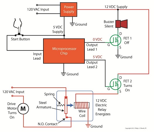
Figure 1
Figure 1 shows a very basic representation of a microprocessor control system that operates three components, an electric relay (shown in the blue box), buzzer, and light. These three components have a certain degree of internal electrical resistance, annotated as RR, RB, and RL respectively. This is because they are made of materials with inherent imperfections which tend to resist the flow of electric current. Imperfections such as these are unavoidable in any electronic device made by humans, due to impurities within metals and irregularities in molecular structure. When the three components are activated by the microprocessor chip via field effect transistors, denoted as FET 1, 2 and 3 in the diagram, their resistances are connected to the supply circuit. In other words, RR, RB, and RL create a combined level of resistance in the supply circuit by their connectivity to it. If a single component were to be removed from the circuit, its internal resistance would also be removed, resulting in a commensurate decrease in total resistance. The greater the total resistance, the more restriction there is to current flow, denoted as I. The greater the resistance, the more I is caused to decrease. In contrast, if there is less total resistance, I increases. The result of changing current flow resistance is that it causes the unregulated power supply output voltage to change. This is all due to an interesting phenomenon known as Ohm’s Law, represented as this within engineering circles: V = I × R where, V is the voltage supplied to a circuit, I is the electrical current flowing through the circuit, and R is the total electrical resistance of the circuit. So, according to Ohm’s Law, when I and R change, then V changes. Next time we’ll apply Ohm’s Law to a simplified unregulated power supply circuit schematic. In so doing we’ll discover the mathematical explanation to the change in current flow and accompanying change in power supply output voltage we’ve been discussing. ____________________________________________ |

Transistors – Voltage Regulation
Sunday, July 22nd, 2012| Electrical voltage flow and water flow have a lot in common. They’re both affected by fluctuations in supply, fluctuations which can adversely impact both performance and equipment integrity. Take for example a sprinkler that fails to cover a designated section of lawn due to heavy neighborhood demand. Everybody wants to water on the weekend when it’s been 90 degrees all week, and low water pressure is the result. There are times when it’s hard to get a glass of water. By contrast in the winter months, when water demands tend to be lower, water supplies are plentiful. This scenario of varying water pressure is analogous to what sometimes occurs within electric circuits.
In my previous blog article on wall warts, I described the operation of a simple power supply consisting of a transformer, diode bridge, and capacitor. Together, these components converted 120 volts alternating current (VAC) to 12 volts direct current (VDC). The wall wart power supply is fine for many applications, however it is unregulated, meaning if there are any sudden surges in power, such as spikes or dips caused by lightning strikes or other disturbances on the electric utility system, there could be problems.
Take for example a power supply that is used in conjunction with sensitive digital logic chips, like the one used in my x-ray film processor design shown in my last blog article. These chips are designed to run optimally on a constant voltage, like 5 VDC, and when that doesn’t happen input signals can fail to register with the computer program and cause a variety of problems, such as output signals turning on and off at will. In the film processor the drive motor may start at the wrong time or get stuck in an on modality. If power surges are high enough, microprocessor chips can get damaged, compromising the entire working unit. The output voltage of an unregulated power supply can also vary in response to power demand, just as when sprinklers don’t have sufficient water flow to cover a section of lawn. Demand for power can change within a circuit when electrical components like relays, lights, and buzzers are turned on and off by digital logic chips. Next time we’ll take a look at a basic concept of electrical engineering known as “Ohm’s Law” and how it governs the variable output voltage response of unregulated power supplies.
____________________________________________ |


