|
During 6th grade science we had a chapter on Simple Machines, and my textbook listed a common lever as an example, the sort that can be used to make work easier. Its illustration showed a stick perched atop a triangular shaped stone, appearing very much like a teeter-totter in the playground. A man was pushing down on one end of the stick to move a large boulder with the other end. Staring at it I thought to myself, “That doesn’t look like a machine to me. Where are its gears?” That day I learned about more than just levers, I learned to expect the unexpected when it comes to machines. Last time we learned that under patent law the machine referred to in federal statute 35 USC § 101 includes any physical device consisting of two or more parts which dynamically interact with each other. We looked at how a purely mechanical machine, such as a diesel engine, has moving parts that are mechanically linked to dynamically interact when the engine runs. Now, lets move on to less obvious examples of what constitutes a machine. Would you expect a modern electronic memory stick to be a machine? Probably not. But, under patent law it is. It’s an electronic device, and as such it’s made up of multiple parts, including integrated circuit chips, resistors, diodes, and capacitors, all of which are soldered to a printed circuit board where they interact with one another. They do so electrically, through changing current flow, rather than through physical movement of parts as in our diesel engine. A transformer is an example of another type of machine. An electrical machine. Its fixed parts, including wire coils and steel cores, interact dynamically both electrically and magnetically in order to change voltage and current flow. Electromechanical, the most complex of all machine types, includes the kitchen appliances in your home. They consist of both fixed and moving parts, along with all the dynamic interactions of mechanical, electronic, and electrical machines. Next time we’ll continue our discussion on the second hurtle presented by 35 USC § 101, where we’ll discuss what is meant by article of manufacture. ___________________________________________ |
Posts Tagged ‘electronic’
Determining Patent Eligibility – Part 4, Machines of a Different Kind
Sunday, April 28th, 2013Transistors – Voltage Regulation Part XII
Sunday, October 7th, 2012|
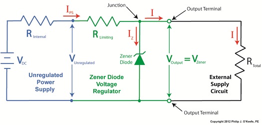
Let’s continue our discussion with regard to the example circuit discussed last time and see how the Zener diode works in tandem with the limiting resistor to control current flow and hold the output voltage at a constant level. Figure 1
To recap our discussion from last week, the unregulated power supply portion of the circuit in Figure 1 generates an unregulated voltage, VUnregulated. Then the Zener diode, which acts as a voltage regulator, takes in VUnregulated and converts it into a steady output voltage, VOutput. Because these output terminals are connected to the ends of the Zener diode, VOutput is equal to the voltage put out by it, denoted as VZener. The Zener diode, an excellent negotiator of current, is essentially involved in a constant trade off, substituting electric current that originates in the unregulated power supply portion of the circuit for voltage, VOutput, that will serve to power the external supply circuit. In other words, the Zener diode draws as much current, IZ, through it as it needs, its objective being to keep VOutput at a constant level, and it will continue to provide this constant output, despite the fact that VUnregulated varies considerably. So, where does the current IZ come from? From IPS, that is, the current flowing from the unregulated power supply area, as shown in Figure 1. IPS flows through the limiting resistor to a junction within the circuit. At this junction, IZ splits off from IPS and continues on to the Zener diode, while current I splits off from IPS on its way to the total internal resistance, RTotal, in the external supply circuit. What this means is that when you add IZ and I together, you get IPS. Mathematically speaking this is represented as: IPS = IZ + I Why solve for IPS? We’ll see why this is important when we revisit Ohm’s Law next week and gain a fuller understanding of how IPS, VUnregulated, VZener, and RLimiting relate to each other with regard to the Zener diode. ____________________________________________ |


