| Back in the early 1970s my dad, a notorious tightwad, coughed up several hundred dollars to buy his first portable color television. That was a small fortune back then. The TV was massive, standing at 24 inches wide, 18 inches high, and 24 inches deep, and weighing in at about 50 pounds. I think the only thing that made this behemoth “portable” was the fact that it had a carrying handle on top.
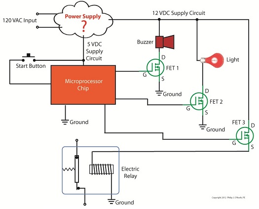
A major reason for our old TV being so big and clunky was of course due to limitations in technology of the time. Many large, heavy, and expensive electronic components were needed to make it work, requiring a lot of space for the circuitry. By comparison, modern flat screen televisions and other electronic devices are small and compact because advances in technology enable them to work with far fewer electronic components. These components are also smaller, lighter, and cheaper. Last time we looked at the components of a simple unregulated power supply to see how it converts 120 volts alternating current (VAC) to 12 volts direct current (VDC). We discovered that the output voltage of the supply is totally dependent on the design of the transformer, because the transformer in our example can only produce one voltage, 12 VDC. This of course limits the supply’s usefulness in that it is unable to power multiple electronic devices requiring two or more voltages, such as we’ll be discussing a bit further down. Now let’s illustrate this power supply limitation by revisiting our microprocessor control circuit example which we introduced in a previous article in this series on transistors. Figure 1
In Figure 1 we have to decide what kind of power to supply to the circuit, but we have a problem. Sure, the unregulated power supply that we just discussed is up to the task of providing the 12 VDC needed to supply power for the buzzer, light, and electric relay. But let’s not forget about powering the microprocessor chip. It needs only 5 VDC to operate and will get damaged and malfunction on the higher 12 VDC the current power supply provides. Our power supply just isn’t equipped to provide the two voltages required by the circuit. We could try and get around this problem by adding a second unregulated power supply with a transformer designed to convert 120 VAC to 5 VAC. But, reminiscent of the circuitry in my dad’s clunky old portable color TV, the second power supply would require substantially more space in order to accommodate an additional transformer, diode bridge, and capacitor. Another thing to consider is that transformers aren’t cheap, and they tend to have some heft to them due to their iron cores, so more cost and weight would be added to the circuit as well. For these reasons the use of a second power supply is a poor option. Next time we’ll look at how adding a transistor voltage regulator circuit to the supply results in cost, size, and weight savings. It also results in a more flexible and dependable output voltage. ____________________________________________ |
Posts Tagged ‘light’
Transistors – Voltage Regulation Part VIII
Sunday, September 9th, 2012Transistors – Voltage Regulation Part V
Sunday, August 19th, 2012| I’m sure you’ve seen the television commercials warning about harmful interactions between prescription medications. By the same token electronic circuitry can also be adversely affected by certain combinations of electrical components, as we’ll discuss in today’s blog.
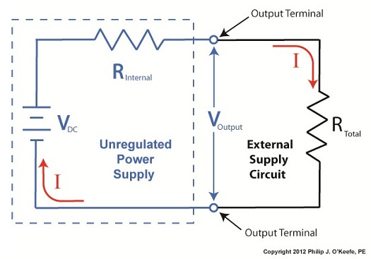
Last time we looked at a circuit schematic containing an unregulated power supply. This power supply was connected to an external supply circuit containing a number of components such as electric relays, buzzers, and lights. Each of these components has a resistance factor, and combined they have a total resistance of RTotal. We saw that when RTotal increases, the electrical current, I, decreases, and when RTotal decreases, I increases. In contrast to this increasing/decreasing activity of the total resistance RTotal, the fixed internal resistance of the unregulated power supply, RInternal, doesn’t fluctuate. Let’s explore Ohm’s Law further to see how the static effect of RInternal combines with the changing resistance present in RTotal to adversely affect the unregulated power supply output voltage, VOutput, causing it to fluctuate. Figure 1
In Figure 1 RTotal and RInternal are operating in series, meaning they are connected together like sausage links. In this configuration their two resistances add together as if they were one larger resistor. Generally speaking, Ohm’s Law sets out that the current, I, flowing through a resistor in an electrical circuit equals the voltage, V, applied to the resistor divided by the resistance R, or: I = V ÷ R In the case of the circuit represented in Figure 1, the resistors RInternal and RTotal are connected in series within the circuit, so their resistances must be added together to arrive at a total power demand. Voltage is applied to these two resistors by the same voltage source, VDC. So, for the circuit as a whole Ohm’s Law would be written as: I = VDC ÷ (RInternal + RTotal) But, Ohm’s Law can also be applied to individual parts within the circuit, just as it can be applied to a single kitchen appliance being operated on a circuit shared with other appliances. Let’s see how this applies to our example circuit’s RTotal next week. ____________________________________________ |
Transistors – Voltage Regulation Part II
Sunday, July 29th, 2012| I joined the Boy Scouts of America as a high schooler, mainly so I could participate in their Explorer Scout program and learn about electronics. I will forever be grateful to the Western Electric engineers who volunteered their personal time to stay after work and help me and my fellow Scouts build electronic projects. The neatest part of the whole experience was when I built my first regulated power supply with their assistance inside their lab. But in order to appreciate the beauty of a regulated power supply we must first understand the shortcomings of an unregulated one, which we’ll begin to do here.
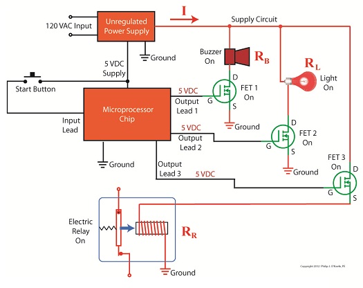
Last time we began to discuss how the output voltage of an unregulated power supply can vary in response to power demand, just as when sprinklers don’t have sufficient water flow to cover a section of lawn. Let’s explore this concept further. Figure 1
Figure 1 shows a very basic representation of a microprocessor control system that operates three components, an electric relay (shown in the blue box), buzzer, and light. These three components have a certain degree of internal electrical resistance, annotated as RR, RB, and RL respectively. This is because they are made of materials with inherent imperfections which tend to resist the flow of electric current. Imperfections such as these are unavoidable in any electronic device made by humans, due to impurities within metals and irregularities in molecular structure. When the three components are activated by the microprocessor chip via field effect transistors, denoted as FET 1, 2 and 3 in the diagram, their resistances are connected to the supply circuit. In other words, RR, RB, and RL create a combined level of resistance in the supply circuit by their connectivity to it. If a single component were to be removed from the circuit, its internal resistance would also be removed, resulting in a commensurate decrease in total resistance. The greater the total resistance, the more restriction there is to current flow, denoted as I. The greater the resistance, the more I is caused to decrease. In contrast, if there is less total resistance, I increases. The result of changing current flow resistance is that it causes the unregulated power supply output voltage to change. This is all due to an interesting phenomenon known as Ohm’s Law, represented as this within engineering circles: V = I × R where, V is the voltage supplied to a circuit, I is the electrical current flowing through the circuit, and R is the total electrical resistance of the circuit. So, according to Ohm’s Law, when I and R change, then V changes. Next time we’ll apply Ohm’s Law to a simplified unregulated power supply circuit schematic. In so doing we’ll discover the mathematical explanation to the change in current flow and accompanying change in power supply output voltage we’ve been discussing. ____________________________________________ |


