Posts Tagged ‘pulleys’

Tangential Velocity

Monday, August 14th, 2017

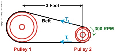
   Last time we introduced the Mechanical Power Formula, which is used to compute power in pulley-belt assemblies, and we got as far as introducing the term tangential velocity, V, a key variable within the Formula.   Today we’ll devise a new formula to compute this tangential velocity.

   Our starting point is the formula introduced last week to compute the amount of power, P, in our pulley-belt example is, again,

P = (T1 – T2) × V                                         (1)

   We already know that P is equal to 4 horsepower, we have yet to determine the belt’s tight side tension, T1, and loose side tension, T2, and of course V, the formula for which we’ll develop today.


Tangential Velocity

Tangential Velocity


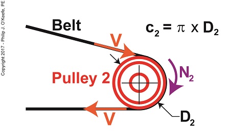
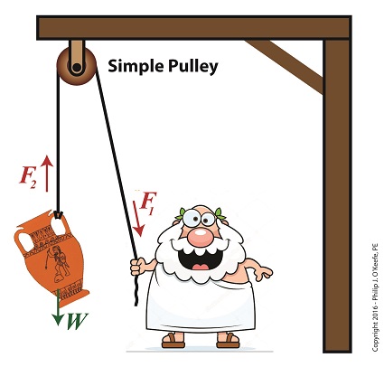
   Tangential velocity is dependent on both the circumference, c2, and rotational speed, N2, of Pulley 2.  The circumference represents the length of Pulley 2’s curved surface.   The belt travels part of this distance as it makes its way from Pulley 2 back to Pulley 1. The rotational speed, N2, represents the rate that it takes for Pulley 2’s curved surface to make one revolution while propelling the belt.   This time period is known as the period of revolution, t2, and is related to N2 by this equation,

N2 = 1 ÷ t2                                                                         (2)

   The rotational speed of Pulley 2 is specified in our example as 300 RPMs, or revolutions per minute, and we’ll denote that speed as N2 in light of the fact it’s referring to speed present at the location of Pulley 2.   As we build the formula, we’ll be converting N2 into velocity, specifically tangential velocity, V, which is the velocity at which the belt operates, this in turn will enable us to solve equation (1).

   Why speak in terms of tangential velocity rather than plain old ordinary velocity?  Because the moving belt’s orientation to the surface of the pulley lies at a tangent in relation to the pulley’s circumference, c2, as shown in the above illustration.   Put another way, the belt enters and leaves the curved surface of the pulley in a straight line.

   Generally speaking, velocity is distance traveled over a period of time, and tangential velocity is no different.  So taking time into account we arrive at this formula,

V = c2 ÷ t2                                                                          (3)

   Since the surface of Pulley 2 is a circle, its circumference can be computed using a formula developed thousands of years ago by the Greek engineer and mathematician Archimedes.   It is,

c2 = π × D2                                                            (4)

where D2 is the diameter of the pulley and π represents the constant 3.1416.

   We now arrive at the formula for tangential velocity by combining equations (3) and (4),

V = π × D2 ÷ t2                                                    (5)

   Next time we’ll plug numbers into equation (5) and solve for V.

Copyright 2017 – Philip J. O’Keefe, PE

Engineering Expert Witness Blog

____________________________________


The Angle of Wrap Formula

Wednesday, July 5th, 2017

    Last time we introduced a scenario involving a hydroponics plant powered by a gas engine and multiple pulleys.   Connecting the pulleys is a flat leather belt.  Today we’ll take a step further towards determining what width that belt needs to be to maximize power transmission efficiency.   We’ll begin by revisiting the two T’s of the Euler-Eytelwein Formula and introducing a formula to determine a key variable, angle of wrap.

 The Angle of Wrap Formula

The Angle of Wrap Formula

    We must start by calculating T1, the tight side tension of the belt, which is the maximum tension the belt is subjected to.   We can then calculate the width of the belt using the manufacturer’s specified safe working tension of 300 pounds per inch as a guide.   But first we’ll need to calculate some key variables in the Euler-Eytelwein Formula, which is presented here again,

T1 = T2× eθ)                                                       (1)

    We determined last time that the coefficient of friction, μ, between the two interfacing materials of the belt and pulley are, respectively, leather and cast iron, which results in a factor of 0.3.

    The other factor shown as a exponent of e is the angle of wrap, θ, and is calculated by the formula,

θ = (1802α) × (π ÷ 180)                                     (2)

    You’ll note that this formula contains some unique terms of its own, one of which is familiar, namely π, the other, α, which is less familiar.   The unnamed variable α is used as shorthand notation in equation (2), to make it shorter and more manageable.   It has no particular significance other than the fact that it is equal to,

α = sin-1((D1 – D2) ÷ 2x)                                       (3)

If we didn’t use this shorthand notation for α, equation (2) would be written as,

θ = (1802(sin-1((D1 – D2) ÷ 2x))) × (π ÷ 180)      (3a)

That’s a lot of parentheses!

    Next week we’ll get into some trigonometry when we discuss the diameters of the pulleys, which will allow us to solve for the angle of wrap.


Copyright 2017 – Philip J. O’Keefe, PE

Engineering Expert Witness Blog

____________________________________


Johann Albert Eytelwein, Engineering Trailblazer

Monday, March 20th, 2017

    They say necessity is the mother of invention, and today’s look at an influential historical figure in engineering bears that out.   Last week we introduced Leonhard Euler and touched on his influence to the science of pulleys.   Today we’ll introduce his contemporary and partner in science, Johann Albert Eytelwein, a German mathematician and visionary, a true engineering trailblazer whose contributions to the blossoming discipline of engineering led to later studies with pulleys.

 Johann Albert Eytelwein, Engineering Trailblazer

Johann Albert Eytelwein, Engineering Trailblazer


    Johann Albert Eytelwein’s experience as a civil engineer in charge of the dikes of former Prussia led him to develop a series of practical mathematical problems that would enable his subordinates to operate more effectively within their government positions.   He was a trailblazer in the field of applied mechanics and their application to physical structures, such as the dikes he oversaw, and later to machinery.   He was instrumental in the founding of Germany’s first university level engineering school in 1799, the Berlin Bauakademie, and served as director there while lecturing on many developing engineering disciplines of the time, including machine design and hydraulics.   He went on to publish in 1801 one of the most influential engineering books of his time, entitled Handbuch der Mechanik (Handbook of the Mechanic), a seminal work which combined what had previously been mere engineering theory into a means of practical application.

    Later, in 1808, Eytelwein expanded upon this work with his Handbuch der Statik fester Koerper (Handbook of Statics of Fixed Bodies), which expanded upon the work of Euler.   In it he discusses friction and the use of pulleys in mechanical design.  It’s within this book that the famous Euler-Eytelwein Formula first appears, a formula Eytelwein derived in conjunction with Euler.   The formula delves into the usage of belts with pulleys and examines the tension interplay between them.

    More on this fundamental foundation to the discipline of engineering next time, with a specific focus on pulleys.

Copyright 2017 – Philip J. O’Keefe, PE

Engineering Expert Witness Blog

____________________________________


Leonhard Euler, a Historical Figure in Pulleys

Thursday, March 9th, 2017

    Last time we ended our blog series on pulleys and their application within engineering as aids to lifting.   Today we’ll embark on a new focus series, pulleys used in mechanical devices.   We begin with some history, a peek at Swiss scientist and mathematician Leonhard Euler, a historical figure credited to be perhaps the greatest mathematician of the 18th Century.


Leonhard Euler, a Historical Figure in Pulleys

Leonhard Euler, a Historical Figure in Pulleys


    Euler is so important to math, he actually has two numbers named after him.   One is known simply as Euler’s Number, 2.7182, most often notated as e, the other Euler’s Constant, 0.57721, notated γ, which is a Greek symbol called gamma.   In fact, he developed most math notations still in use today, including the infamous function notation, f(x), which no student of elementary algebra can escape becoming intimately familiar with.

    Euler authored his first theoretical essays on the science and mathematics of pulleys after experimenting with combining them with belts in order to transmit mechanical power.   His theoretical work became the foundation of the formal science of designing pulley and belt drive systems.   And together with German engineer Johann Albert Eytelwein, Euler is credited with a key formula regarding pulley-belt drives, the Euler-Eytelwein Formula, still in use today, and which we’ll be talking about in depth later in this blog series.

    We’ll talk more about Eytelwein, another important historical figure who worked with pulleys, next time.

Copyright 2017 – Philip J. O’Keefe, PE

Engineering Expert Witness Blog

____________________________________


da Vinci’s Tribometre; a Historical Look at Pulleys and Friction

Saturday, January 28th, 2017

   In our blog series on pulleys we’ve been discussing the effects of friction, subjects also studied by Leonardo da Vinci, a historical figure whose genius contributed so much to the worlds of art, engineering, and science.   The tribometre shown in his sketch here is one of history’s earliest recorded attempts to understand the phenomenon of friction.   Tribology, according to the Merriam-Webster Dictionary, is “a study that deals with the design, friction, wear, and lubrication of interacting surfaces in relative motion.”   Depicted in da Vinci’s sketch are what appear to be pulleys from which dangle objects in mid-air.

da Vinci's Tribometre; a Historical Look at Pulleys and Friction

da Vinci’s Tribometre; a Historical Look at Pulleys and Friction

    Copyright 2017 – Philip J. O’Keefe, PE

Engineering Expert Witness Blog

____________________________________


Pulleys Make Santa’s Job Easier

Monday, December 19th, 2016

  Happy Holidays from EngineeringExpert.net, LLC and the Engineering Expert Witness Blog.Pulleys Make Santa's Job Easier

Pulleys Make Santa’s Job Easier


 Copyright 2016 – Philip J. O’Keefe, PE

Engineering Expert Witness Blog

____________________________________


The Simple Pulley Gives Us a Lift

Friday, July 8th, 2016

    Lifting heavy objects into position always presents a challenge, whether it’s a mom lifting a toddler to her hip or a construction worker lifting work materials to great heights.   During my career as an engineering expert I’ve dealt with similar challenges, some of which were handled quite nicely by incorporating a simple pulley, which we introduced last time, into my design.   But sometimes, due to certain restrictions, the addition of a simple pulley into the works isn’t enough to get the job done.   We’ll take a look at one of the restrictions working against the use of a simple pulley today.

    The simple pulley is believed to have first been used by the Greeks as far back as the 9th Century BC.   Back then it would have come in handy to lift cargo aboard ships, hoist sails on masts, and lift building materials high off the ground to supply workmen during the construction of temples and other marvels of ancient architecture.   In other words, pulleys literally saved ancient workers thousands of steps when it came to lifting things off the ground.

    Let’s return to ancient times for a moment to get an understanding of the mechanics behind the workings of the simple pulley as put to use in a basic lifting application.

 The Simple Pulley Gives Us a Lift

The Simple Pulley Gives Us a Lift


    With a simple pulley, the tension force F1 applied to the rope by the pull-er is equal to the tension force F2 exerted upon the object, the pull-ee.   Once lifted off the ground, these forces are also equal to the object’s weight, W, which gravity works upon to return the lifted object to its previous position on the ground.  All these forces come to bear upon whatever’s doing the pulling.   If this pull-er happens to be a human, then the simple pulley’s effectiveness to lift things is directly proportionate to that human’s strength.   In the case of the toga’d figure above, that would be about 10 pounds.   It’s this caveat that limits the usefulness of the simple pulley when relying on human power alone, particularly when it’s employed to lift extremely heavy objects like marble pillars.   A single human isn’t up to the task.

    Next time we’ll see how ancient Greeks overcame this limitation of the simple pulley by managing to cut in half the amount of brute force required to lift heavy objects.

Copyright 2016 – Philip J. O’Keefe, PE

Engineering Expert Witness Blog

____________________________________


Magic as Performed by Pulleys

Friday, June 17th, 2016

    Ever seen that old movie where they’re lifting a grand piano to the top floor of a tall building with ropes?   The huge piano dangles precariously in mid air by the ropes, which are attached to a rather simple looking wheeled device that’s situated at the top of the building.   As men on the ground tug on the ropes, they hoist the piano higher and higher by increments of inches as the wheeled device the rope is threaded through spins madly.   The piano’s formidable size appears to magically levitate off the ground, like in the famous magician’s trick.   That object with the spinning wheel is a pulley, a rather simple device which I as an engineering expert have often made use of in my designs.

So Where's The Pulley?

So Where’s The Pulley?


    We’ll be talking about the various types of pulleys and their uses in future blogs, beginning with an exploration of a simple pulley.

Copyright 2016 – Philip J. O’Keefe, PE

Engineering Expert Witness Blog

____________________________________