|
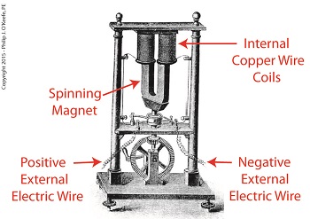
As an engineering expert with 14 years’ electric utility experience, I’ve dealt with all types of electrical power generators, including many similar to the dynamo that James Prescott Joule used in his Experiment With Electricity. Today we’ll look inside Joule’s dynamo and see how it contributed to creating electricity as well as another of Joule’s discoveries, the Joule Heating Effect. Dynamo-Circa Early 19th Century In Joule’s Experiment With Electricity, the dynamo was powered by a steam engine, which enabled the dynamo’s shaft to spin. As it spun, the magnet located inside the dynamo also spun, thus creating a rotating magnetic field that surrounded the dynamo’s internal copper wire coils. The interaction between the magnetic field and wire produced electric current which flowed inside the coils. The current ultimately made its way out of the dynamo by way of external wires, to which any number of devices could be powered when attached. The net result was the engine’s mechanical energy had been converted into electrical. To learn more about the process of producing electricity with magnets see my blog on, Coal Power Plant Fundamentals – The Generator. As electrical energy flowed through the dynamo’s wiring, some of it was converted into heat energy. This was due to resistance posed by impurities present in the makeup of the wire, impurities which served to impede the overall flow of electric current. When electrons flowing through the wire collided with these impediments, they caused heat to build up inside the wire, a phenomenon which came to be known as the Joule Heating Effect. To read more on electrical resistance and Joule heating go to my blog, Wire Size and Electric Current. The net result of Joule’s Experiment With Electricity was to further prove the link between chemical, heat, mechanical and electrical energies as set out in the Law of Conservation of Energy. And I suspect that knowledge was later put to use by Joule’s family for the betterment of their brewery business. Next time we’ll use Joule’s experimental findings in conjunction with de Coriolis’ Kinetic Energy Formula to quantify the energy of the falling coffee mug we’ve been watching.
Copyright 2015 – Philip J. O’Keefe, PE Engineering Expert Witness Blog ____________________________________ |
Posts Tagged ‘electrical resistance’
Joule’s Dynamo – The Joule Heating Effect
Saturday, October 24th, 2015Transistors – Voltage Regulation Part VII
Monday, September 3rd, 2012| Back when television had barely escaped the confines of black and white transmission there was a men’s clothing store commercial whose slogan still sticks in my mind, “Large and small, we fit them all.” It’s a nice concept, but unfortunately the same doesn’t always apply to electronic power supplies.
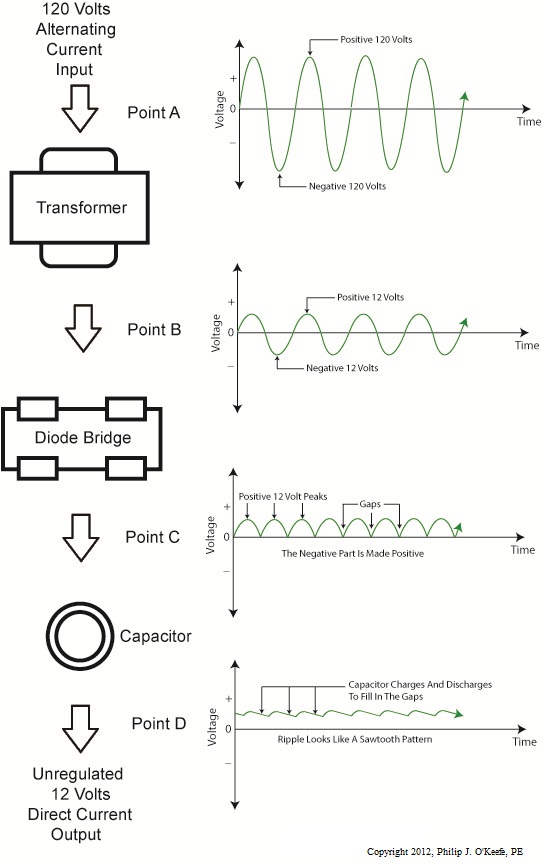
Last time we learned that when the electrical resistance changes on an unregulated power supply its output voltage changes proportionately. This makes it unsuitable for powering devices like microprocessor chips, which require an unchanging voltage to operate properly. Now let’s look at another shortcoming of unregulated power supplies, that being how one supply can’t fit both large and small voltage requirements. Figure 1 shows the components of a simple unregulated power supply. Figure 1
The diagram illustrates the voltage changes taking place as electric current passes through the supply’s four components, which ultimately results in the conversion of 120 volts alternating current (VAC) into 12 volts direct current (VDC). First the transformer converts the 120 VAC from the wall outlet to the 12 volts required by most electronic devices. These voltages are shown at Points A and B. The voltage being put out by the transformer results in waves of energy which alternate between a positive maximum value, then to zero, and finally to a maximum negative value. But we want our power supply to produce 12 VDC. By VDC, I mean voltage that never falls to zero and stays at a positive 12 volts direct current consistently. This is when the diode bridge and capacitor come into play. The diode bridge consists of four electronic components, the diodes, which are connected together to form a bridge and uses semiconductor technology to transform negative voltage from the transformer into positive. The result is a series of 12 volt peaks as shown at Point C. But we still have the problem of zero voltage gaps between each peak. You see, over time the voltage at Point C of Figure 1 keeps fluctuating between 0 volts and positive 12 volts, and this is not suitable to power most electronics, which require a steady VDC current. We can get around this problem by feeding voltage from the diode bridge into the capacitor. When we do that, we eliminate the zero voltage gaps between the peaks. This happens when the capacitor charges up with electrical energy as the voltage from the diode bridge nears the top of a peak. Then, as voltage begins its dive back to zero the capacitor discharges its electrical energy to fill in the gaps between peaks. In other words it acts as a kind of reserve battery. The result is the rippled voltage pattern observed at Point D. With the current gaps filled in, the voltage is now a steady VDC. The output voltage of the unregulated power supply is totally dependant on the design of the transformer, which in this case is designed to convert 120 volts into 12 volts. This limits the power supply’s usefulness because it can only supply one output voltage, that being 12 VDC. This voltage may be insufficient for some electronics, like those often found in microprocessor controlled devices where voltages can range between 1.5 and 24 volts. Next time we’ll illustrate this limitation by revisiting our microprocessor control circuit example and trying to fit this unregulated power supply into it. ____________________________________________ |
Wire Size and Electric Current
Sunday, March 13th, 2011| Whether or not you live or work in a city, you are probably aware of rush hour traffic and how frustrating it can be. As a matter of fact, this traffic is the number one reason many choose to live within cities providing public transportation. Instead of watching the cars pile up in front of you, you can be checking your email or reading the paper. And no matter where you live, you’ve probably encountered a narrow one-lane road at some time. If this road were to be spotted with traffic lights and double parked cars, the resulting frustration would reach a new high, one which has you craving the freedom of a crowded three-lane expressway. At least there’s the possibility of movement there.
Generally, the wider the road and the fewer the impediments, the better traffic will flow. The problems presented by vehicular traffic are analogous to those present in electrical wires. For both, obstructions are impediments to flow. You see, the thicker the metal is in a wire, the more electrical current it can carry. But before we explore why, let’s see how electric wires are classified. If you’ve ever spent any time hanging around a hardware store looking at the goodies, you’ve probably come across wire gauge numbers, used to categorize wire diameter. American Wire Gauge (AWG) is a standardized wire gauge system, used in North American industry since the latter half of the 19th Century. Handy as it is, the AWG gauge numbering system seems to go against logic, because as a wire’s diameter increases, its gauge number decreases. For example, a wire gauge number of 8 AWG has a diameter of 0.125 inches, while a gauge number of 12 AWG has a diameter of 0.081 inches. To make things easier on those who need to know this type of information, wire diameter is tabulated for each AWG gauge number and readily available in engineering reference books. So what does this have to do with electric current? To begin with, the larger the AWG number, the less current it can safely carry. If we turn to an engineering reference book, and look up information relating to an 8 AWG insulated copper wire, we find that it can safely carry an electrical current of 50 amperes, while a 12 AWG insulated copper wire can safely carry only 25 amperes. This information allows us to make important and relevant design decisions regarding a myriad of things, from electrical wiring in electronic devices, to appliances, automobiles, and buildings. So, why are bigger wires able to carry more current? Well, as you’ve heard me say before, no wire is a perfect conductor of electricity, but some metals, take copper for instance, are better conductors than others, say steel. But even the best conductors are inherently full of impurities and imperfections that resist the flow of electricity. This electrical resistance acts much like traffic lights and double parked cars that impede the flow of traffic. The larger the diameter of the wire, the less electrical resistance is present. The logic here is simple. Wire that is larger allows more paths for electrical current to flow around impurities and imperfections. The congestion present in rush hour traffic results in travel delays and hot tempers, and heat is also present in electric wires that face resistance to electricity flow. If the resistance to electric current flow is high enough, it can cause overheating. Road rage within the wires is a possibility, and if the wires get hot enough, electrical insulation can melt and burn, creating a fire. Known as the “Joule heating” effect, this phenomenon is responsible for its share of building fires. We’ll learn more about Joule heating and how wires are sized to keep electrical current flow within safe limits next week. Until then, try to keep out of traffic. _____________________________________________
|
A Few Words About Electric Shocks
Sunday, July 26th, 2009 For an electric shock to occur, a person must become a part of an electrical circuit in such a way that electric current passes over their skin or through their body. Under certain conditions, even momentary contact with an energized metal object can result in serious injury and even death. According to an article in the American Journal of Industrial Medicine:
From an engineering viewpoint, the body’s electrical resistance is an important variable. Electrical resistance of an object is a measure of how freely electrical current can flow across the object when a voltage is applied across it. Resistance is measured in units called “Ohms.” Resistance of a person’s body can depend on skin dryness, perspiration level, thickness of the skin, the distance that the electrical current travels through the skin, and other factors. The typical human body has a hand-to-hand electrical resistance somewhere between 1,000 and 2,000 Ohms, but resistance across other parts of the body can be much higher. There is a wide variation in body resistance between individuals, so the same voltage level may result in different effects. Most electrical injuries occur from alternating current (AC) at levels above 50 Volts at the low frequencies typically maintained by electric utilities. The North American utilities normally generate power at a frequency of 60 cycles per second. The “cycles per second” unit of frequency is also referred to as “Hertz,” usually abbreviated as “Hz.” At 60Hz frequency, the threshold for perception occurs with electrical currents as low as 0.0001 Amps. The “can’t let go” electrical current for adults is approximately 0.010 to 0.015 Amps. This is the current that causes involuntary muscle contractions severe enough to prevent the person from letting go of the source of the electrical shock. Electric currents as low as 0.050 Amps at 120V, 60Hz, have been known to cause death. Just to give you an idea of how small that current is… a table lamp with one 40 Watt incandescent bulb draws 0.333 Amps from a 120 Volt, 60 Hz household electrical outlet! In the interest of electrical safety, the National Electrical Code (NEC) considers 0.005 Amps at 120V, 60Hz to be the safe upper limit for children and adults. ____________________________________________________________________
|


