Posts Tagged ‘spinning flywheel’

Moment of Inertia in a Flywheel

Monday, November 6th, 2017

    Last time we arrived at a general formula to compute the kinetic energy, KE, contained within the totality of a spinning flywheel made up of numerous parts.   Today we’ll discuss the terms in that formula, which encompasses a phenomenon of flywheels known as moment of inertia.

Moment of Inertia in a Flywheel

Moment of Inertia in a Flywheel


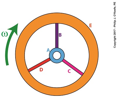
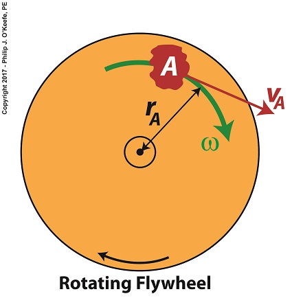
   The kinetic energy formula we’ve been working with is, again,

KE = ½ × Σ[m × r2] × ω2                           (1)

    The bracketed part of this equation makes reference to spinning flywheels comprised of one or more parts, and that’s what we’ll be focusing on today.   The symbol Σ is the Greek letter sigma, standard engineering shorthand notation used to represent the sum of all terms and mathematical operations contained within the brackets.

    Our illustration shows we have five parts to consider:  a hub, three spokes and a rim, and label them A, B, C, D, and E respectively.   Each part has its own mass, m, and is a unique distance, r, from the flywheel’s center of rotation.   The flywheel’s angular velocity is represented by ω.

   For our flywheel of parts A through E our expanded equation becomes,

Σ[m × r2] = [mA × rA2] + [mB × rB2] + [mC × rC2] + [mD × rD2] + [mE × rE2]      (2)

    Equation (2) represents the sum total of moments of inertia contained within our flywheel.  It’s a numerical representation of the flywheel’s degree of resistance to changes in motion.

    The more mass a flywheel has, the greater its moment of inertia.  When at rest this greater moment of inertia means it will take more effort to return it to motion.   But once in motion the flywheel’s greater moment of inertia will make it harder to stop.   That’s because there’s a lot of kinetic energy stored within its spinning mass, and the heavier a flywheel is, the more kinetic energy it contains.   In fact, for any given angular velocity ω, a large and heavy flywheel stores more kinetic energy than a smaller, lighter flywheel.

    But there’s more to a flywheel’s moment of inertia than just mass.   What’s really important is how that mass is distributed. We’ll get into that next time when we discuss torque.

Copyright 2017 – Philip J. O’Keefe, PE

Engineering Expert Witness Blog

____________________________________


Two Types of Velocity Associated With a Spinning Flywheel

Thursday, October 19th, 2017

    Anyone who has spun a potter’s wheel is appreciative of the smooth motion of the flywheel upon which they form their clay, for without it the bowl they’re forming would display irregularities such as unattractive bumps.   The flywheel’s smooth action comes as a result of kinetic energy, the energy of motion, stored within it.   We’ll take another step towards examining this phenomenon today when we take our first look at calculating this kinetic energy.   To do so we’ll make reference to the two types of velocity associated with a spinning flywheel, angular velocity and linear velocity, both of which engineers must negotiate anytime they deal with rotating objects.

    Let’s begin by referring back to the formula for calculating kinetic energy, KE.  This formula applies to all objects moving in a linear fashion, that is to say, traveling a straight path.   Here it is again,

KE = ½ × m × v2

where m is the moving object’s mass and v its linear velocity.

    Flywheels rotate about a fixed point rather than move in a straight line, but determining the amount of kinetic energy stored within a spinning flywheel involves an examination of both its angular velocity and linear velocity.   In fact, the amount of kinetic energy stored within it depends on how fast it rotates.

    For our example we’ll consider a spinning flywheel, which is basically a solid disc.   For our illustrative purposes we’ll divide this disc into hypothetical parts, each having a mass m located a distance r from the flywheel’s center of rotation.   We’ll select a single part to examine and call that A.

Two Types of Velocity Associated With a Spinning Flywheel

Two Types of Velocity Associated With a Spinning Flywheel


    Part A has a mass, mA, and is located a distance rA from the flywheel’s center of rotation.   As the flywheel spins, part A rides along with it at an angular velocity, ω, following a circular path, shown in green.   It also moves at a linear velocity, vA, shown in red.   vA represents the linear velocity of part A measured at any point tangent to its circular path.  This linear velocity would become evident if part A were to become disengaged from the flywheel and cast into the air, whereupon its trajectory would follow a straight line tangent to its circular path.

    The linear and angular velocities of part A are related by the formula,

vA = rA × ω

    Next time we’ll use this equation to modify the basic kinetic energy formula so that it’s placed into terms that relate to a flywheel’s angular velocity.   This will allow us to define a phenomenon at play in the flywheel’s rotation, known as the moment of inertia.


Copyright 2017 – Philip J. O’Keefe, PE

Engineering Expert Witness Blog

____________________________________