|
Last time we learned that the geometric shape specific to spur gear teeth is known as an involute profile. Today we’ll look at the geometry behind this profile and the very specific place at which gear teeth meet, known as the point of contact. The transmission of mechanical energy between meshed gears may seem on its face to be straightforward, after all their gears are interlaced and interact with one another. But their interaction involves some rather complex geometry, because forces are directed in a peculiar fashion between the teeth of the driving and driven gears. Let’s consider the following illustration to get a better understanding.
 Meshed Gear Tooth Geometry
As we learned previously in this series, the pitch circle of a gear is an imaginary arc passing through each tooth between their top and bottom lands. The pitch circles of the driving and driven gears are represented by heavy red dashed lines in the illustration. To ensure proper alignment and smooth action between gear teeth during rotation, the gears are spaced so that their pitch circles just meet but never intersect. This specific point is known as the point of contact. It is the only point at which gears will come into actual physical contact with one another, and it provides just enough contact so that when the driving gear turns in one direction, say clockwise, its teeth exert pressure upon the driven gear teeth, forcing it to move in the opposite direction, counterclockwise. The forces which come into play at the point of contact are represented in the illustration by a black dot with oppositional blue arrows extending from it. These arrows represent the opposing mechanical forces, F1 and F2 , which act upon the teeth when they make contact. We’ll learn more about the effect of those forces next time when we follow a locomotive from a stationary position into one of movement.
_______________________________________ |
Posts Tagged ‘gear teeth’
Meshed Gear Teeth and Their Point of Contact
Monday, January 27th, 2014Spur Gear Tooth Geometry and the Involute Curve
Sunday, January 19th, 2014|
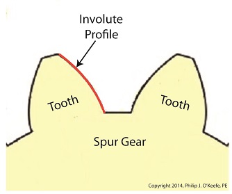
Last time we learned how spur gears mesh together to form a gear train and we examined a train consisting of just two gears, one being the driving gear, the other the driven gear. Today we’ll take a look at the geometry behind the smooth functioning of modern spur gear teeth when we identify their peculiar shape to be that of an involute curve. The curved profile of spur gear teeth conforms to a type of mathematical curve found in geometry known as an involute. The involute profile of a spur gear tooth is shown in red below. The mathematical notion of the involute was first presented in 1673 by Dutch mathematician Christiaan Huygens, in his book, Horologium Oscillatorium. Huygens’ book presents his studies on clock pendulums and the applied mathematics he used in an effort to predict their often erratic motion on ships at sea. His book ultimately dealt with far more than this, resulting in a treatise on the mathematical properties of the involutes of curves. To see how an involute curve is formed, we’ll conduct a simple experiment. One end of string is attached with a tack to a circular object, like the yellow rod shown in the following illustration. The other end of string has a red ball attached to it.
 Forming An Involute Curve If we grab the ball and pull the string taught while wrapping the string around the rod, the ball’s path will form an involute curve due to the incremental shortening of the string that occurs as it wraps around the rod. Next time we’ll see how the involute profile of gear teeth contributes to efficient mechanical energy transmission in gear trains. _______________________________________ |

Gear Trains
Monday, January 13th, 2014|
Last time we covered the basic terminology of spur gears. Today we’ll see how they interact with one another to form a gear train, such as the one depicted below.
 Meshing Spur Gears Form A Gear Train A gear train is formed when the teeth of two or more gears mesh and work together for the purpose of powering a mechanical device. A gear train can consist of as little as two gears, but trains can be so large as to contain dozens of gears, depending on the complexity of the device they are powering. But no matter how many gears are employed, there are certain key features that are shared by every gear train assembly. First, one gear within the train must be attached to a shaft rotated by a source of mechanical energy, such as an engine or electric motor. This gear is called the driving gear. The second requirement of a gear train is that at least one gear other than the driving gear is mounted to the shaft of a rotating machine part. This gear is called the driven gear.
 Locomotive Gear Train Consisting Of Two Gears The illustration above shows an exploded view of a locomotive gear train assembly consisting of two gears. The driving gear is mounted to the shaft of an electric traction motor. The driven gear is mounted to the locomotive’s axle. When a motor is attached to the axle, the two gears mesh together. The traction motor converts electrical energy into mechanical energy, which is supplied to the driving gear via the spinning motor’s shaft. The teeth of the driving gear then transmit the motor’s mechanical energy to the teeth of the driven gear, which then turn the locomotive’s wheels. It’s just one of countless operations that can be performed with gear train assemblies. Next time we’ll examine the geometry behind modern spur gear tooth design. _______________________________________ |


