Posts Tagged ‘centrifugal pump’

Centrifugal Pumps Can Create Vacuums

Thursday, February 8th, 2018

    Last time we performed an engineering experiment that demonstrated how we can lower the boiling point of water inside a lidded pot without applying heat if we use a vacuum pump to lower the pot’s internal pressure.   We discovered that when pressure was lowered to 0.25 pounds per square inch (PSI), the water inside the pot turned to steam at a mere 59ºF, which initiated the cavitation process.   Today we’ll see how centrifugal pumps can also create vacuums to initiate cavitation.


Centrifugal Pumps Can Create Vacuums

Centrifugal Pumps Can Create Vacuums


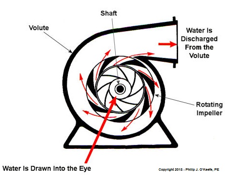
    As we learned in a past blog, centrifugal pumps contain rotating impellers within a housing called a volute.   This housing has an inlet, known as an eye, where water flows into the pump from a pipe, and an outlet, known as a discharge, where water flows out of the pump.   The centrifugal pump creates a vacuum by mimicking the action of sucking soda through a straw.    The spinning impeller draws water into the housing by creating low pressure at the inlet, and if the pressure gets low enough, we’ll recreate what happened in our vacuum pump and pot experiment.   Water will boil at temps far lower than normal boiling point of 212 ºF.   Just as in our experiment, if pressure is lowered to 0.23 PSI, water present at the pump inlet will boil at 59ºF, causing thousands of tiny steam bubbles to form and the pump to cavitate.

    They’re just tiny bubbles, so what harm can they do? We’ll find out next time.

opyright 2018 – Philip J. O’Keefe, PE

Engineering Expert Witness Blog

____________________________________


Boiler Feed Pumps Experience Cavitation

Wednesday, January 3rd, 2018

    Shortly after I graduated with my engineering degree I worked as a power plant engineer at an electric utility.   One day I was walking through the plant and heard a loud racket coming from the boiler feel pumps.   These are the massive centrifugal pumps that deliver pressurized water to the boiler.   The water is transformed into steam to drive steam turbines and spin electrical generators, which ultimately results in electrical power.   The noise was so loud, it sounded like rocks were being ground up.   I asked a coworker what was going on, and he replied matter-of-factly, “The pumps are cavitating.

Boiler Feed Pumps Experience Cavitation

Boiler Feed Pumps Experience Cavitation


    So what exactly is cavitation?   We’ll find out next time when we explore the mechanics of this noisy phenomenon as it applies to boiler feed pumps and other centrifugal pumps.

opyright 2017 – Philip J. O’Keefe, PE

Engineering Expert Witness Blog

____________________________________


Centrifugal Pumps

Sunday, May 16th, 2010

     Last week we focused on various types of positive displacement pumps.  Today we’ll take a look at centrifugal pumps.  See Figure 1.

Figure 1 – A Centrifugal Pump

     Just like the positive displacement pumps we talked about last week, centrifugal pumps have rotating parts as well, but that’s where their similarities end.  Unlike positive displacement pumps that take “bites” out of liquid before trapping it between moving parts, centrifugal pumps rely on kinetic energy to move liquid in a continuous stream.  Kinetic energy is the energy of motion, and in the case of the centrifugal pump kinetic energy is developed by rotating parts within the pump and transferred to the liquid contained within the pump.  In other words, the liquid is moved through the pump by means of centrifugal force.

     To illustrate this concept, we can tie a rope to the handle of a bucket that has a small hole punched in the bottom.  Now, you know what will happen if you fill the bucket with water…  There’s a hole in the bucket, Dear Liza, Dear Liza…  That’s right, the water will just dribble out of the hole, thanks to gravity.  But before we fix the hole as Liza suggests, let’s do an experiment.  Pick up the rope and spin the bucket around as fast as you can in a circle.  You’ll notice that this rapid spinning creates centrifugal force, resulting in a rather powerful stream of water shooting from the hole.  The faster you spin the bucket, the stronger the stream.

     When it comes to centrifugal pumps, the idea is basically the same.  The objective is to forcefully spin water around in a circle, thus ejecting it from the pump.  This is accomplished with a rotating part called an impeller.  See Figure 2.

Figure 2 – Cutaway View of a Centrifugal Pump    


     In our illustration the impeller is attached to a shaft that’s powered by some source of mechanical energy, such as an electric motor.  The water enters the pump at the center of the rotating impeller, referred to as the “eye.”  The water then slides over the face of the impeller, moving from the center to its edge due to the action of centrifugal force.  That force pushes it off the impeller and into the pump housing.  You’ll note that the housing has a special shape, called a “volute.”  This volute looks a lot like a spiraled snail shell.  The shape of the volute helps direct the water coming off the impeller into an opening in the side of the pump where it is discharged.  The faster the pump impeller rotates, the more kinetic energy the water picks up from the impeller.

     This ends our discussion on pumps.  Next time, we’ll move on to a new topic of discussion, braking systems.

_____________________________________________

A Pump By Any Other Name…

Monday, May 10th, 2010

     Pumps are all around us.  They keep our drinking water flowing, the cooling water circulating in your car’s engine, and even your blood flowing.  They’re essential in many aspects of our lives, but most of us don’t think too much about them.  For our discussion let’s put them into two categories:  positive displacement pumps and centrifugal pumps.  This week, we’ll focus on positive displacement pumps.

     Positive displacement pumps, as their name implies, displace a quantity of liquid with each complete cycle of movement.  This takes place when moving parts of the pump take “bites” out of the liquid at the inlet, then force them to exit through the outlet.  A familiar example of a positive displacement pump is the type of hand operated water pump that’s commonly found in campgrounds.  See Figure 1.


Figure 1 – A Positive Displacement Pump

     This type of pump is known as a reciprocating positive displacement pump.  By reciprocating, I mean that the moving parts travel back and forth in a straight line during its operation.  Let’s see how it works by referring to the cutaway view in Figure 2.  


Figure 2 – Cutaway View of the Pump Shown in Figure 1 

     In the cutaway view, the pump’s piston and internal check valve are shown, and there’s another check valve in the bottom of the pump housing.  When you pull up on the handle, the piston moves down into the water in the pump housing, and the pressure caused by this movement forces the check valve in the bottom to slam closed, while the check valve above is forced open.  This causes water movement to flood through the open check valve and fill up the space above the piston.  When you push down on the handle, the opposite happens.  The piston is made to move upward.  The upward acceleration of the water above the piston causes the check valve on the piston to slam shut, and this traps the water above it.  As the piston moves back up, a suction is created below, which causes the check valve in the bottom of the housing to pop open and more water is drawn up into the space below the piston.  Eventually, when the piston gets high enough, the water trapped on top of it will flow out of the spigot.

    Another type of positive displacement pump is represented by a rotary pump.  These pumps operate in a circular motion to move a volume of liquid with each revolution of the pump shaft.  This is done by trapping liquid between moving parts, such as gears, lobes, vanes, or screws, and the stationary pump housing itself.  

     To show how this works, refer to the gear pump shown in Figure 3.  Its gear teeth mesh together in the middle of the pump, blocking the flow from going straight through and trapping it within the spaces formed by rotating gear teeth and the pump housing.  It’s like the water is being forced through a turnstile.

Figure 3 – A Cutaway View of a Gear Pump

 
     Next week, we’ll talk about centrifugal pumps and how they move liquids along using centrifugal force.
_____________________________________________