| My first car was a used 1963 Dodge 880. It was reliable for the most part, but one day when I stepped on the brake in a supermarket parking lot, nothing happened. I began to roll down an incline, and I struggled to steer around the maze of parked cars in the lot. After what seemed to be an eternity I managed to navigate my way out of the lot into an adjacent cornfield. The soft ground and corn stalks finally brought me to a stop. I later discovered that the reason my brakes failed is because their linings had completely worn away.
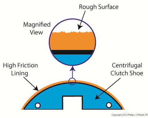
Like the brakes in cars, centrifugal clutch shoes also have linings as shown in Figure 1. Brake linings are typically made of a rough, high friction materials, such as ceramic compounds. These materials are bonded to the brake shoes, or in the case of clutches, to the clutch shoes. When centrifugal force comes into play, pressing the clutch shoes against the inside wall of the clutch housing, the roughness of the linings provides a good grip, preventing slippage between the shoes and the housing. Figure 1
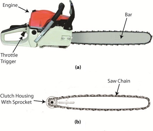
As we learned in previous articles, slip between the clutch shoes and clutch housings can create problems. In our grass trimmer for example, we learned that slippage reduces the amount of power the engine can effectively transmit to the cutter head. It also tends to produce a lot of heat. This heat can adversely effect the clutch springs and cause clutch failure. Although the high friction lining of the clutch shoes prevents most slippage, it can still occur, as when the throttle is depressed and engine speed increases beyond idle. There is some slipping as the clutch shoes first engage with the clutch housing, and it will continue until the engine speed increases to the point where centrifugal force causes the clutch shoes to firmly press into the clutch housing. Slippage also occurs when gasoline powered tools are subjected to operating stress. Figure 2 shows two views of a chainsaw. The first view is complete, the second shows the chain and clutch housing in isolation. Figure 2
With the engine housing removed, we see that the saw chain is connected to a sprocket located on the centrifugal clutch housing. This sprocket is similar to those that engage the chains on bicycle wheels. Now suppose someone decides to use the chainsaw to cut a green, sap-filled log. To make matters worse, let’s suppose the chainsaw has a dull saw chain. If you’ve ever tried doing this, you know that the sticky, sappy wood will eventually gum up the chain and stop it from moving. Since the chain is connected to the clutch housing, it stops as well. However the clutch shoes, which are driven by the engine, keep trying to move the gummed-up clutch housing, because the engine’s power is enough to overcome some of the friction. The result is that the shoes slip uselessly inside the housing. Over time, continued slippage will cause the clutch shoes’ high friction lining to wear away. Once the lining is gone the clutch shoes will slip excessively, even when the gasoline powered tool is being employed to perform the lightest task. That’s because slipping prevents a good portion of the engine’s power from being transmitted to the cutting head. That’s it for our series on centrifugal clutches. Next we’ll be discussing transistors, how they’re used in electronic controls to switch things on and off and perform other functions. ____________________________________________ |
Posts Tagged ‘throttle trigger’
Mechanical Power Transmission – Centrifugal Clutch Shoe Wear
Sunday, June 3rd, 2012Mechanical Power Transmission – Putting the Centrifugal Clutch Together
Sunday, April 29th, 2012| I’ve never been one to enjoy table top puzzles, yet I love to examine the way mechanical things fit together. Manipulating parts to see how they interrelate to form an operational system is a pastime I very much enjoy. In fact, I spend many evenings at my work bench doing just this. I often become so engrossed in the activity I forget what time it is. The result is yet another night without TV. So sad…
Last week we looked at how a centrifugal clutch mechanism operates when it’s coupled to a gasoline engine shaft spinning at idle speed, and then we depressed the engine throttle trigger to speed things up. Let’s now introduce a new component called the clutch housing to see how it interfaces with the clutch mechanism to drive the cutter head in a grass trimmer. Figure 1
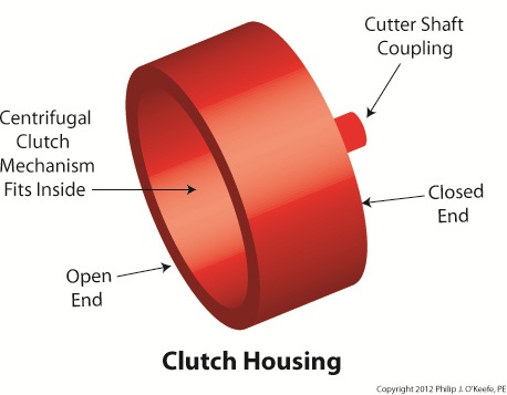
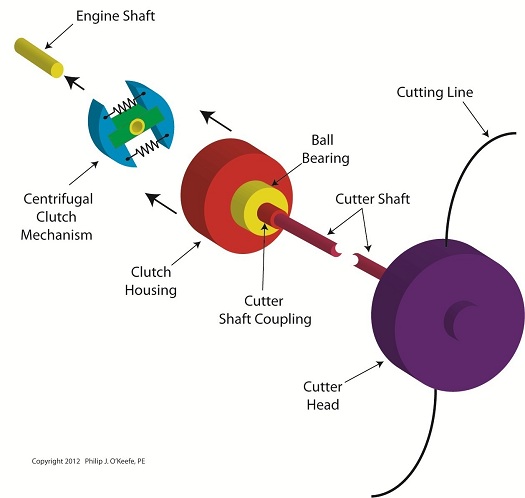
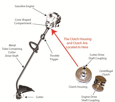
The clutch housing shown in Figure 1 resembles a rather short cup. One end is open, the other closed. Figure 2 shows the closed end of the clutch housing connected to the cutter shaft’s coupling. On the cutter shaft coupling resides a ball bearing which enables the clutch housing to both spin freely and act as a support for the clutch housing. The open end of the clutch housing allows the clutch mechanism to fit neatly inside. Figure 2
Next time we’ll put the assembly shown in Figure 2 into operation. First we’ll examine how the centrifugal clutch mechanism and clutch housing operate with the engine at idle speed, then compare that to the engine operating at actual cutting speed. ____________________________________________
|
Mechanical Power Transmission – The Centrifugal Clutch in Operation
Sunday, April 22nd, 2012| Just the other day I unexpectedly experienced the effects of centrifugal force while driving home from the grocery store. The checker had packed my entire order into one bag, making it top heavy. Then en route someone cut me off at an intersection, and I had to make a sharp turn to avoid a crash. During this maneuver centrifugal force came into play, forcing my grocery bag out of its centered position on the front seat next to me. It lurched into the passenger’s door, fell over, and spilled its contents onto the floor. Fortunately the eggs didn’t get smashed.
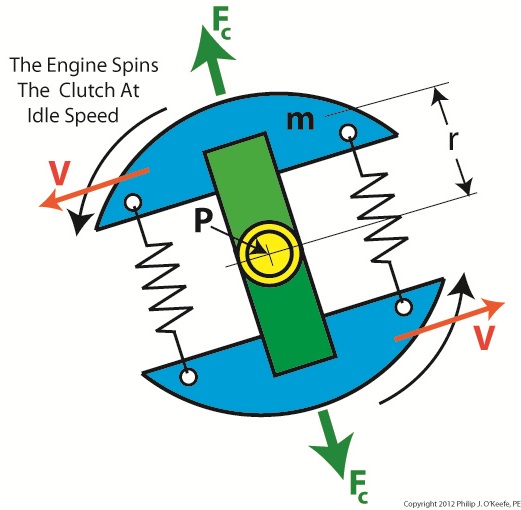
In previous articles we identified the component parts of a centrifugal clutch mechanism and learned how centrifugal force makes objects spinning in a circular path about a fixed point move outward. We can now explore what happens when we couple a centrifugal clutch mechanism to the engine of a grass trimmer. Figure 1 depicts the spinning clutch mechanism of a gas engine when it’s just been started and is operating at a slow idle speed. Figure 1
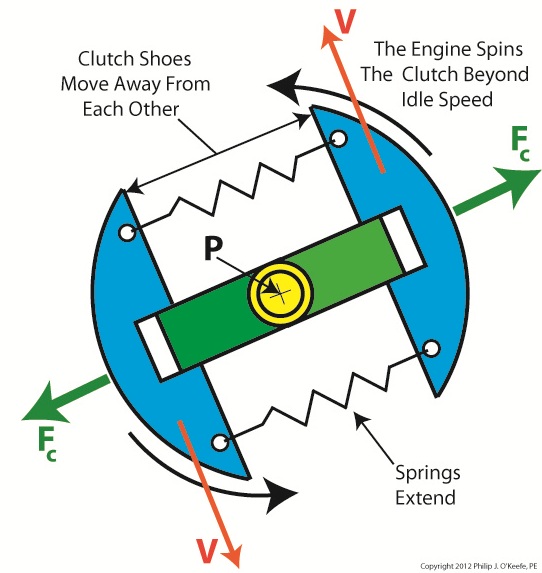
Like the red ball in my previous article on centrifugal force, the blue centrifugal clutch shoes each have a mass m. They spin around a fixed point P, situated at the center of the yellow engine shaft coupling. Point P is located a distance r from the center of each shoe. The shoes in motion have a tangential velocity V, and in accordance with Sir Isaac Newton’s Law of Centrifugal Force, the force Fc acts upon each shoe, causing them to want to pull out from the center of the mechanism, away from the fixed point. Since idle speed is rather slow, however, the centrifugal force exerted upon the shoes isn’t strong enough to overcome the tension of the two springs and the coils connecting them remain coiled, holding the shoes tightly in position on the green boss. So what happens when we press the throttle trigger on the gas engine and cause the engine to speed up? See Figure 2. Figure 2
Figure 2 shows the clutch mechanism spinning at an increased velocity. The tangential velocity V increases, and according to Newton’s law, the centrifugal force Fc acting on the clutch shoes increases as well. The force is so strong that it overcomes the tension in the springs and they extend. The clutch shoes are caused to move out and away from fixed point P, as well as from each other, traveling along the ends of the boss. When we remove our finger from the throttle trigger, the engine will slow down and return to idle speed. The centrifugal force will decrease and the springs will pull the shoes back towards fixed point P. The mechanism will return to its previous state, as shown in Figure 1. Next time we’ll insert the centrifugal clutch mechanism into the clutch housing to see how mechanical power is transmitted from the engine to the cutter head in our grass trimmer. ____________________________________________
|
