Posts Tagged ‘pulley diameter’

Belt Velocity

Monday, August 21st, 2017

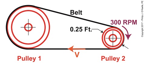
   Last time we developed an equation to compute tangential velocity, V, of the belt in our example pulley and belt system.   Today we’ll plug numbers into this equation and arrive at a numerical value for this belt velocity.

Belt Velocity

Belt Velocity


   The equation we’ll be working with is,

V = π × D2 ÷  t2                                                        (1)

where, D2 is the diameter of Pulley 2 and π represents the constant 3.1416. We learned that Pulley 2’s period of revolution, t2, is related to its rotational speed, N2, which represents the time it takes for it to make one revolution and is represented by this equation,

N2 = 1 ÷ t2                                                                            (2)

   We’ll now solve for the belt’s velocity, V, using known values, starting off with rearranging terms so we can solve for t2,

t2 = 1 ÷ N                                                                         (3)

   We were previously given that N2 is 300 RPM, or revolutions per minute, so equation (3) becomes,

t2 = 1 ÷ 300 RPM = 0.0033 minutes                         (4)

   This tells us that Pulley 2 takes 0.0033 minutes to make one revolution in our pulley-belt assembly.

   Pulley 2’s diameter, D2, was previously determined to be 0.25 feet.    Inserting this value equation (1) becomes,

 V = π × (0.25 feet) ÷ (0.0033 minutes)                  (5)

 V = 237.99 feet/minute                                         (6)


   We’ve now determined that the belt in our pulley-belt assembly zips around at a velocity of 237.99 feet per minute.

   Next time we’ll apply this value to equation (6) and determine the belt’s tight side tension, T1.

Copyright 2017 – Philip J. O’Keefe, PE

Engineering Expert Witness Blog

____________________________________


Pulley Diameter Determines Speed

Saturday, April 8th, 2017

    Soon after the first pulleys were used with belts to transmit mechanical power, engineers such as Leonhard Euler and Johann Albert Eytelwein discovered that the diameter of the pulleys used determined the speed at which they rotated.   This allowed for a greater diversity in mechanical applications.   We’ll set up an examination of this phenomenon today.

    Last time we introduced this basic mechanical power transmission system consisting of a driving pulley, a driven pulley, and a belt, which we’ll call Situation A.

 A Driven Pulley’s Larger Diameter Determines a Slower Speed

A Driven Pulley’s Larger Diameter Determines a Slower Speed


    In this situation, the rotating machinery’s driven pulley diameter is larger than the electric motor’s driving pulley diameter.   The result is the driven pulley turns at a slower speed than the driving pulley.

    Now let’s say we need to speed the rotating machinery up so it produces more widgets per hour.   In that case we’d make the driven pulley smaller, as shown in Situation B.

 A Driven Pulley’s Smaller Diameter Determines a Faster Speed

A Driven Pulley’s Smaller Diameter Determines a Faster Speed


    With the smaller diameter driven pulley, the rotating machinery will operate faster than it did in Situation A.

    Next week we’ll introduce the Pulley Speed Ratio Formula, which mathematically defines this phenomenon.

 Copyright 2017 – Philip J. O’Keefe, PE

Engineering Expert Witness Blog

____________________________________