|
Inertia. It’s the force that keeps us in bed after the alarm has rung. It seems to have a life of its own, and today we’ll see how it comes into play in keeping other stationary objects at rest. Last time we identified a specific point of contact between spur gear teeth in a gear train and introduced the opposing forces, F1 and F 2, generated there. Today we’ll see what these forces represent, identifying one of them as inertia.
So where do these forces come from? They’re forces generated by different means that converge at the same point of contact, the point at which gear teeth mesh. They follow a very specific geometric path to meet there, an imaginary straight line referred to as the line of action. F1 is always generated by a source of mechanical energy. In our locomotive example introduced earlier in this blog series that source is an electric traction motor, upon which a driving gear is mounted. When the motor is energized, a driving force F1 is generated, which causes gear teeth on the driving gear to push against gear teeth of the driven gear. Force F2 is not as straightforward to understand, because it’s not generated by a motor. Instead, it’s the resisting force that the weight of a stationary object poses against its being moved from an at-rest position, known as inertia. The heavier the object, the more inertia it presents with. Trains, of course, are extremely heavy, and to get them to move a great deal of inertia must be overcome. Inertia is also a factor in attempting to stop objects already in motion. To get a stationary locomotive to move, mechanical energy must be transmitted from the driving gear that’s attached to its traction motor, then on to the driven gear attached to its axle. At their point of contact, the driving force of the motor, F1, is met by the resisting force of inertia, F2. In order for the train to move, F1 must be greater than F2. If F1 is less than or equal to F2, then the train won’t leave the station. Next week we’ll animate our static image and watch the interplay between gear teeth, taking note of the line of action during their movement.
_______________________________________ |
Posts Tagged ‘locomotive’
Overcoming Inertia
Monday, February 3rd, 2014
Meshed Gear Teeth and Their Point of Contact
Monday, January 27th, 2014|
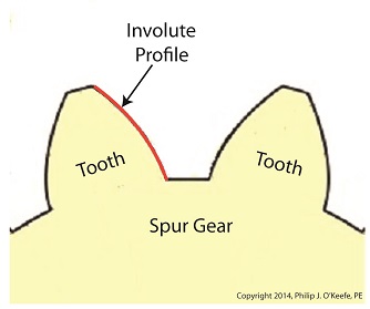
Last time we learned that the geometric shape specific to spur gear teeth is known as an involute profile. Today we’ll look at the geometry behind this profile and the very specific place at which gear teeth meet, known as the point of contact. The transmission of mechanical energy between meshed gears may seem on its face to be straightforward, after all their gears are interlaced and interact with one another. But their interaction involves some rather complex geometry, because forces are directed in a peculiar fashion between the teeth of the driving and driven gears. Let’s consider the following illustration to get a better understanding.
 Meshed Gear Tooth Geometry
As we learned previously in this series, the pitch circle of a gear is an imaginary arc passing through each tooth between their top and bottom lands. The pitch circles of the driving and driven gears are represented by heavy red dashed lines in the illustration. To ensure proper alignment and smooth action between gear teeth during rotation, the gears are spaced so that their pitch circles just meet but never intersect. This specific point is known as the point of contact. It is the only point at which gears will come into actual physical contact with one another, and it provides just enough contact so that when the driving gear turns in one direction, say clockwise, its teeth exert pressure upon the driven gear teeth, forcing it to move in the opposite direction, counterclockwise. The forces which come into play at the point of contact are represented in the illustration by a black dot with oppositional blue arrows extending from it. These arrows represent the opposing mechanical forces, F1 and F2 , which act upon the teeth when they make contact. We’ll learn more about the effect of those forces next time when we follow a locomotive from a stationary position into one of movement.
_______________________________________ |
Spur Gear Tooth Geometry and the Involute Curve
Sunday, January 19th, 2014|
Last time we learned how spur gears mesh together to form a gear train and we examined a train consisting of just two gears, one being the driving gear, the other the driven gear. Today we’ll take a look at the geometry behind the smooth functioning of modern spur gear teeth when we identify their peculiar shape to be that of an involute curve. The curved profile of spur gear teeth conforms to a type of mathematical curve found in geometry known as an involute. The involute profile of a spur gear tooth is shown in red below. The mathematical notion of the involute was first presented in 1673 by Dutch mathematician Christiaan Huygens, in his book, Horologium Oscillatorium. Huygens’ book presents his studies on clock pendulums and the applied mathematics he used in an effort to predict their often erratic motion on ships at sea. His book ultimately dealt with far more than this, resulting in a treatise on the mathematical properties of the involutes of curves. To see how an involute curve is formed, we’ll conduct a simple experiment. One end of string is attached with a tack to a circular object, like the yellow rod shown in the following illustration. The other end of string has a red ball attached to it.
 Forming An Involute Curve If we grab the ball and pull the string taught while wrapping the string around the rod, the ball’s path will form an involute curve due to the incremental shortening of the string that occurs as it wraps around the rod. Next time we’ll see how the involute profile of gear teeth contributes to efficient mechanical energy transmission in gear trains. _______________________________________ |

Gear Trains
Monday, January 13th, 2014|
Last time we covered the basic terminology of spur gears. Today we’ll see how they interact with one another to form a gear train, such as the one depicted below.
 Meshing Spur Gears Form A Gear Train A gear train is formed when the teeth of two or more gears mesh and work together for the purpose of powering a mechanical device. A gear train can consist of as little as two gears, but trains can be so large as to contain dozens of gears, depending on the complexity of the device they are powering. But no matter how many gears are employed, there are certain key features that are shared by every gear train assembly. First, one gear within the train must be attached to a shaft rotated by a source of mechanical energy, such as an engine or electric motor. This gear is called the driving gear. The second requirement of a gear train is that at least one gear other than the driving gear is mounted to the shaft of a rotating machine part. This gear is called the driven gear.
 Locomotive Gear Train Consisting Of Two Gears The illustration above shows an exploded view of a locomotive gear train assembly consisting of two gears. The driving gear is mounted to the shaft of an electric traction motor. The driven gear is mounted to the locomotive’s axle. When a motor is attached to the axle, the two gears mesh together. The traction motor converts electrical energy into mechanical energy, which is supplied to the driving gear via the spinning motor’s shaft. The teeth of the driving gear then transmit the motor’s mechanical energy to the teeth of the driven gear, which then turn the locomotive’s wheels. It’s just one of countless operations that can be performed with gear train assemblies. Next time we’ll examine the geometry behind modern spur gear tooth design. _______________________________________ |
Transistors – Voltage Regulation Part III
Tuesday, August 7th, 2012| When my daughter was seven she found out about Ohm’s Law the hard way, although she didn’t know it. She had accidentally bumped into her electric toy train, causing its metal wheels to derail and fall askew of the metal track. This created a short circuit, causing current to flow in an undesirable direction, that is, through the derailed wheels rather than along the track to the electric motor in the locomotive as it should.
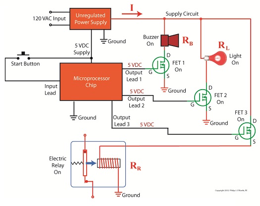
What happened during the short circuit is that the bulk of the current began to follow through the path of least resistance, that of the derailed wheels, rather than the higher resistance of the electric motor. Electric current, always opportunistic, will flow along its easiest course, in this case the short, thick metal of the wheels, rather than work its way along the many feet of thin metal wire of the motor’s electromagnetic coils. With its wheels sparking at the site of derailment the train had become an electric toaster within seconds, and the carpet beneath the track began to burn. Needless to say, mom wasn’t very happy. In this instance Ohm’s Law was at work, with a decidedly negative outcome. The Law’s basic formula concerning the toy train would be written as: I = V ÷ Rwhere, I is the current flowing through the metal track, V is the track voltage, and R is the internal resistance of the metal track and locomotive motor, or in the case of a derailment, the metal track and the derailed wheel. So, according to the formula, for a given voltage V, when the R got really small due to the derailment, I got really big. But enough about toy trains. Let’s see how Ohm’s Law applies to an unregulated power supply circuit. We’ll start with a schematic of the power supply in isolation.
Figure 1The unregulated power supply shown in Figure 1 has two basic aspects to its operation, contained within a blue dashed line. The dashed line is for the sake of clarity when we connect the power supply up to an external circuit which powers peripheral devices later on. The first aspect of the power supply is a direct current (DC) voltage source, which we’ll call VDC. It’s represented by a series of parallel lines of alternating lengths, a common representation within electrical engineering. And like all electrical components, the power supply has an internal resistance, such as discussed previously. This resistance, notated RInternal, is the second aspect of the power supply, represented by another standard symbol, that of a zigzag line. Finally, the unregulated power supply has two output terminals. These will connect to an external supply circuit through which power will be provided to peripheral devices. Next time we’ll connect to this external circuit, which for our purposes will consist of an electric relay, buzzer, and light to see how it all works in accordance with Ohm’s Law. ____________________________________________ |

Industrial Control Basics – Thermal Expansion Effect on Overload Relays
Sunday, March 11th, 2012| Imagine driving on steel tires, not rubber. Don’t think it would work too well? On asphalt highways maybe not, but on the steel rails that steam locomotives travel upon, steel wheels work surprisingly well and it’s due in large part to the principles of thermal expansion and the different rates at which metal alloys expand and contract. Allow me to explain by analyzing how a locomotive“tire” is changed.
As you can imagine changing locomotive tires isn’t easy. Firstly, locomotive shop mechanics have to actually build a fire around the steel tire to heat it up. The intense heat causes its steel tire to thermally expand, meaning its steel molecules become energized by the heat and begin to vibrate. This causes the molecules to move away from each other, and this results in the tire actually growing slightly in size. This enlargement is just enough to enable mechanics to slip the tire back onto the locomotive’s wheel. Now in place, the tire is allowed to cool back down to ambient air temperatures. Cooling results in the tire’s steel molecules relaxing and moving closer to each other. The tire shrinks back to its original preheated size and tightly wraps itself around the wheel. Thermal expansion properties of metals comes into play in many other instances, including the workings of motor overload relays. Please refer to Figure 1.
Figure 1
Here overload relay components are shown in the foreground box. We see that the relay includes an electric heater and a set of two peculiar looking curved objects. These are bimetal switch contacts, so named because each is made of two, that’s the “bi” part, metal strips with different thermal properties. These strips are positioned back to back, then bonded together and curved into a shape resembling a question mark. Each of the two metals has different properties, namely, one expands at a faster rate and to a greater extent than the other when heated. This differing rate of expansion is indicative of the two metals’ diverse thermal properties. When the bimetal contact is exposed to heat, one metal strip wants to expand a lot, but it is bonded to the other metal strip which only wants to expand a little. The end result is that their point of contact distorts and changes shape. When allowed to cool back down, the metal strips contract and the contact point returns to its original shape. In our next blog we’ll see how the contact shape changes and why this shape change is important. In Figure 1 the motor is running normally and there is no overload situation. Under these conditions the motor draws electric current within the normal limits of its design. That current also flows through the heater in the overload relay causing it to generate heat, but in this situation the heat change is small enough that it doesn’t affect the bimetal switch contacts and cause them to change shape. The temperature at which the switch contacts will warp depends on the overall design of the overload relay as well as its application. Next time we’ll see what part a motor overload plays in conjunction with the overload relay’s heater and bimetal contacts. ____________________________________________
|


