Posts Tagged ‘current flow’
Sunday, March 25th, 2012
| Last week our kitchen ceiling fan and light combo decided to stop working. We don’t like eating in the dark, so I was compelled to do some immediate troubleshooting. As an engineer with training in the workings of electricity I have a great respect for it. I’m well aware of potential hazards, and I took a necessary precaution before taking things apart and disconnecting wires. I made the long haul down the stairs to the basement, opened the circuit breaker in the electrical panel, and disabled the flow of electricity to the kitchen. My fears of potential electrocution having been eliminated, my only remaining fear was of tumbling off the ladder while servicing the fan.
Just as I took the precaution to disconnect the power supply before performing electrical maintenance in my home, workers in industrial settings must do the same, and a chief player in those scenarios is the motor overload relay discussed last week. It automatically shuts down electric motors when they become overheated. Let’s revisit that example now.
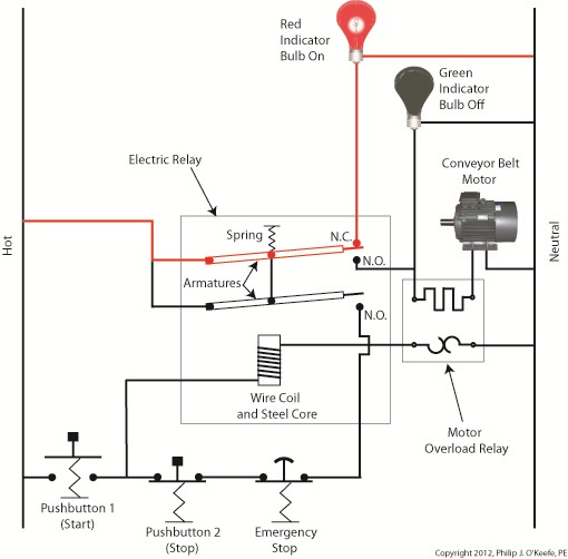
Figure 1
Our diagram in Figure 1 shows electric current flowing through the circuit by way of the red path. Even if this line were shut down, current would continue to flow along the path, because there is no means to disconnect the entire control system from the hot and neutral lines supplying power to it, that is, it is missing disconnect switches. Electric current will continue to pose a threat to workers were they to attempt a repair to the system. Now let’s see how we can eliminate potential hazards on the line.
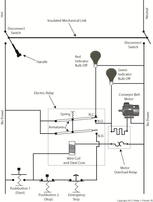
Figure 2
In Figure 2 there is an obvious absence of the color red, indicating the lack of current within the system. We accomplished this with the addition of disconnect switches capable of isolating the motor control circuitry, thereby cutting off the hot and neutral lines of the electrical power supply and along with it the unencumbered flow of electricity.
These switches are basically the same as those seen in earlier diagrams in our series on industrial controls, the difference here is that the two switches are tied together by an insulated mechanical link. This link causes them to open and close at the same time. The switches are opened and closed manually via a handle. When the disconnect switches are both open electricity can’t flow and nothing can operate. Under these conditions there is no risk of a worker coming along and accidentally starting the conveyor motor.
To add yet another level of safety, disconnect switches are often tagged and locked once de-energized. This prevents workers from mistakenly closing them and starting the conveyor while maintenance is being performed. Brightly colored tags alert everyone that maintenance is taking place and the switches must not be closed. The lock that performs this safety function is actually a padlock. It’s inserted through a hole in the switch handle, making it impossible for anyone to flip the switch. Tags and locks are usually placed on switches by maintenance personnel before repairs begin and are removed when work is completed.
Now let’s see how our example control system looks in ladder diagram format.
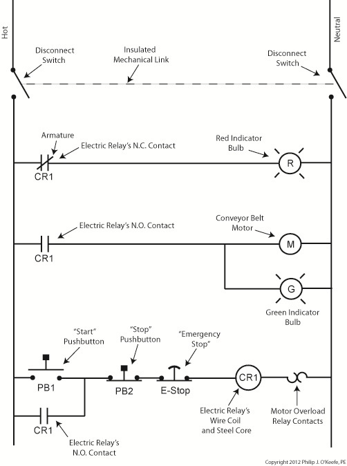
Figure 3
Figure 3 shows a ladder diagram that includes disconnect switches, an emergency stop button, and the motor overload relay contacts. The insulated mechanical link between the two switches is represented by a dashed line. Oddly enough, engineering convention has it that the motor overload relay heater is typically not shown in a ladder diagram, therefore it is not represented here.
This wraps up our series on industrial control. Next time we’ll begin a discussion on mechanical clutches and how they’re used to transmit power from gasoline engines to tools like chainsaws and grass trimmers.
____________________________________________
|
Tags: chainsaw, circuit breaker, circuitry, clutch, control panel, conveyor belt, current flow, death, disconnect switch, electric motor, electric relay, electrical maintenance, electrical panel, electricity, electrocution, emergency stop, engineering expert witness, forensic engineer, hot, indicator bulbs, industrial control system, injury, lawn trimmer, lock, lockout tag out, maintenance worker, motor overheated, neutral, overload relay, overload relay heater, potential hazards, power supply, pushbutton, safety, safety hazard, tag, troubleshooting, wires
Posted in Engineering and Science, Expert Witness, Forensic Engineering, Innovation and Intellectual Property, Personal Injury, Product Liability, Professional Malpractice | Comments Off on Industrial Control Basics – Disconnect Switches
Monday, January 9th, 2012
| It’s a dark and stormy night and you’ve come to the proverbial fork in the road. The plot is about to take a twist as you’re forced to make a decision in this either/or scenario. As we’ll see in this article, an electric relay operates in much the same manner, although choices will be made in a forced mechanical environment, not a cerebral one.
When we discussed basic electric relays last week we talked about their resting in a so-called “normal state,” so designated by industrial control parlance. It’s the state in which no electric current is flowing through its wire coil, the coil being one of the major devices within a relay assembly. Using Figure 3 of my previous article as a general reference, in this normal state a relaxed spring keeps the armature touching the N.C. switch contact. While in this state, a continuous conductive path is created for electricity through to the N.C. point. It originates from the wire on the left side, which leads to the armature pivot point, travels through the armature and N.C. contact points, and finally dispenses through the wire at the right leading from the N.C. contact.
Now let’s look at an alternate scenario, when current is made to flow through the coil. See Figure l, below.

Figure 1
Figure 1 shows the path of electric current as it flows through the wire coil, causing the coil and the steel core to which it’s attached to become magnetized. This magnetization is strong, attracting the steel armature and pulling it towards the steel core, thus overcoming the spring’s tension and its natural tendency to rest in a tension-free state.
The magnetic attraction causes the armature to rotate about the pivot point until it comes to rest against the N.O. contact, thus creating an electrical path en route to the N.O. wire, on its way to whatever device it’s meant to energize. As long as current flows through the wire coil, its electromagnetic nature will attract the armature to it and contact will be maintained with the N.O. juncture.
When current is made to flow through the wire coil, an air gap is created between the armature and the N.C. contact, and this prevents the flow of electric current through the N.C. contact area. Current is forced to follow the path to the N.O. contact only, effectively cutting off any other choice or fork in the road as to electrical path that may be followed. We can see that the main task of an electric relay is to switch current between two possible paths within a circuit, thereby directing its flow to one or the other.
Next time we’ll examine a simple industrial control system and see how an electric relay can be engaged with the help of a pushbutton.
____________________________________________ |
Tags: armature, coil, control relay, control system, current flow, electric current, electric relay, electrical path, electrical relay, electrical switch, electricity, electromagnetic, engineering expert witness, forensic engineering, industrial control, magnetic attraction, N.C., N.C. contact, N.O., N.O. contact, normal state, normally closed, normally open, pushbutton, relay, relay ladder logic, spring, steel core, switch, switch contact, switching current, wire coil
Posted in Engineering and Science, Expert Witness, Forensic Engineering, Innovation and Intellectual Property, Personal Injury, Product Liability, Professional Malpractice | 1 Comment »
Monday, December 26th, 2011
| I always enjoy watching impatient people waiting for an elevator. They press the button, and if it doesn’t come within a few seconds they press it over and over again, as if this will hurry things up. In the end they must resign themselves to the fact that the elevator will operate in its own good time.
Pushbuttons, although simple in appearance like the big, red “Easy” button that’s featured in a certain business supply chain’s commercials, are actually complex behind the scenes. They perform important functions within the industrial control systems of a huge diversity of mechanized equipment.
Last week we introduced ladder diagrams, used to design and document industrial control systems, and we’ll now see how they depict the action of pushbuttons within two commonly used industrial settings, the “normally open” and the “normally closed.”
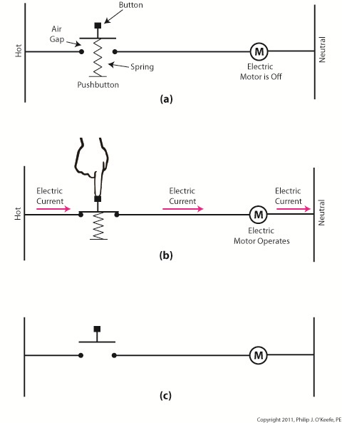
Figure 1
Figure 1(a) shows a pushbutton hooked up to an electric motor. When no one is pressing it a spring in the pushbutton forces the button to rest in the up position, allowing an air gap to exist in the electrical circuit between hot and neutral and preventing current from flowing. This type of switch is characterized as a “normally open” switch in industrial control terminology.
In Figure 1(b) someone depresses the button, compressing its spring and closing the air gap, which allows current to flow and the motor to operate
Figure 1(c) shows the ladder diagram version of 1(a).
Now let’s take a look at Figure 2 to see a different type of pushbutton, one that’s characterized as “normally closed.”
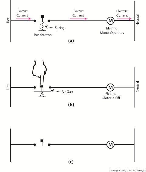 Figure 2 Figure 2
“Normally closed” refers to the fact that when no one is depressing the button, the normal operating position is for the air gap to be absent, allowing electrical current to flow and the motor to operate, as shown in Figure 2(a).
Figure 2(b) shows that an air gap is created when the button is depressed and the spring holding the mechanism into the normally closed position is forced down. This action interrupts electrical current and causes the motor to stop.
Figure 2(c) shows the simplified line drawing version of 2(a).
You can imagine how strained your finger would be if it had to press down on that button with any frequency or duration. Next time we’ll see how electrical relays work alongside pushbuttons to give index fingers a break.
____________________________________________ |
Tags: control system, current flow, electric motor, electrical circuit, engineering expert witness, forensic engineer, hot, industrial control, ladder diagram, machine control, mechanized equipment, motor control, neutral, normally closed, normally open, pushbutton, relay, spring, switch
Posted in Engineering and Science, Expert Witness, Forensic Engineering, Innovation and Intellectual Property, Personal Injury, Product Liability, Professional Malpractice | Comments Off on Industrial Control Basics – Pushbuttons
Sunday, July 3rd, 2011
| Most people aren’t aware of just how important those strange looking wall outlets in our kitchens and bathrooms are, you know, the ones with the little buttons that say Test and Reset. They’re known as GFCI outlets, that is Ground Fault Circuit Interrupters, and given the right set of circumstances they could save your life.
The GFCI equipped wall outlet, like a mighty robot, continuously watches the flow of electrons (electrical current) passing through, always on the lookout for incongruities between the hot and neutral wires, and ready to jump into action when necessary. Say, for example, that one of these GFCI equipped outlets has an appliance plugged into it. While the appliance is in safe use there is nothing for the GFCI robot to do. It simply takes note of the balance of electrons flowing between the hot and neutral conductors, notes that they are equal, and continues to watch for inequalities.
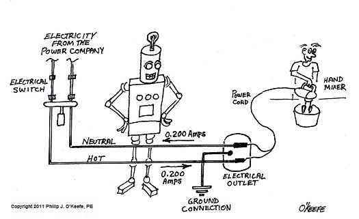 Figure 1 – While the Hand Mixer is Operating Normally, in the GFCI Outlet the Electric Current Flowing in the Hot and Neutral Wires is Equal. The Robot Takes No Action. Figure 1 – While the Hand Mixer is Operating Normally, in the GFCI Outlet the Electric Current Flowing in the Hot and Neutral Wires is Equal. The Robot Takes No Action.
But suppose that there is a problem with the appliance, something that causes a ground fault where the user’s body provides an unintended path to errant electrons flowing from the hot side of the wall outlet. Those errant electrons are supposed to traverse the neutral wire back through the wall outlet from whence they came, but they have become unruly. Not to worry, if you are up to code and have an ever vigilant GFCI on that outlet, the robot will immediately notice the anomaly.
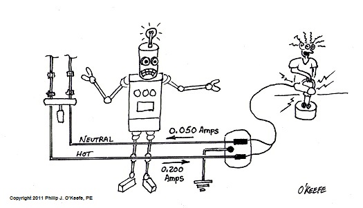
Figure 2 – If a Ground Fault Develops in the Hand Mixer and Some Electric Current Flows Through the User’s Body, Then the Robot Notices a Difference In Current Flowing Through the Hot and Neutral Wires in the GFCI Outlet.
The Mighty Robot of the GFCI doesn’t like the fact that the electrons are out of balance, that there are more of them flowing through the hot wire than returning through the outlet via the neutral wire, so within a fraction of a second it will jump into action to correct things. It hits a lever on a spring loaded mechanism that snaps open an electrical switch connecting the appliance to the hot and neutral sides of the outlet, effectively cutting off the flow of electrons to the appliance. Cut off from power, the appliance ceases to function, but more importantly, the flow of electrons through the user’s body has been stopped before their body incurs injury, or death.
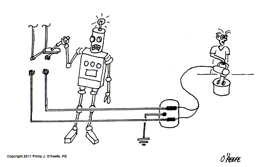
Figure 3- In Response to the Ground Fault, the Robot Opens a Switch in the GFCI Outlet to Cut Off The Flow of Electricity to the Hand Mixer. The Person Operating the Hand Mixer is Saved.
The GFCI robot, having done its job, now goes into a sleep mode. It will be reactivated, ready again for its vigilant watch of errant electrons, when the faulty appliance is unplugged and the Reset button is pressed. This button does what it says, it resets the spring loaded mechanism in the wall outlet, closing the electrical switch, and making the outlet functional again. The GFCI robot immediately goes back into active monitoring mode.
Now it should be noted that as dependable as GFCI outlets are, they can become defective. That’s why they have a Test button. This button should be pressed periodically to see if the robot is still on the job. If all is in order, the Reset button pops out of the outlet, and anything plugged into that outlet will not operate. When you press the Reset button back in, everything should operate again if there are no fault conditions.
Could the GFCI’s Mighty Robot have prevented the unfortunate incidents discussed during my tenure on The Discovery Channel? Stay tuned to find out…
That’s it for GFCI outlets. Next time we’ll take a look at how an invention developed to defend the allies during World War II later morphed into a space age device that cooks our food.
_____________________________________________ |
Tags: appliance, current flow, Discovery Channel, electrical switch, electrocution, electron flow, engineering expert witness, forensic engineer, GFCI, ground, ground fault, ground fault circuit interrupter, hand mixer, hot, neutral, plug, shock hazard, wall outlet
Posted in Engineering and Science, Expert Witness, Forensic Engineering, Personal Injury, Product Liability | Comments Off on GFCI Outlets and The Mighty Robot
Sunday, March 13th, 2011
| Whether or not you live or work in a city, you are probably aware of rush hour traffic and how frustrating it can be. As a matter of fact, this traffic is the number one reason many choose to live within cities providing public transportation. Instead of watching the cars pile up in front of you, you can be checking your email or reading the paper. And no matter where you live, you’ve probably encountered a narrow one-lane road at some time. If this road were to be spotted with traffic lights and double parked cars, the resulting frustration would reach a new high, one which has you craving the freedom of a crowded three-lane expressway. At least there’s the possibility of movement there.
Generally, the wider the road and the fewer the impediments, the better traffic will flow. The problems presented by vehicular traffic are analogous to those present in electrical wires. For both, obstructions are impediments to flow. You see, the thicker the metal is in a wire, the more electrical current it can carry. But before we explore why, let’s see how electric wires are classified.
If you’ve ever spent any time hanging around a hardware store looking at the goodies, you’ve probably come across wire gauge numbers, used to categorize wire diameter. American Wire Gauge (AWG) is a standardized wire gauge system, used in North American industry since the latter half of the 19th Century. Handy as it is, the AWG gauge numbering system seems to go against logic, because as a wire’s diameter increases, its gauge number decreases. For example, a wire gauge number of 8 AWG has a diameter of 0.125 inches, while a gauge number of 12 AWG has a diameter of 0.081 inches. To make things easier on those who need to know this type of information, wire diameter is tabulated for each AWG gauge number and readily available in engineering reference books.
So what does this have to do with electric current? To begin with, the larger the AWG number, the less current it can safely carry. If we turn to an engineering reference book, and look up information relating to an 8 AWG insulated copper wire, we find that it can safely carry an electrical current of 50 amperes, while a 12 AWG insulated copper wire can safely carry only 25 amperes. This information allows us to make important and relevant design decisions regarding a myriad of things, from electrical wiring in electronic devices, to appliances, automobiles, and buildings.
So, why are bigger wires able to carry more current? Well, as you’ve heard me say before, no wire is a perfect conductor of electricity, but some metals, take copper for instance, are better conductors than others, say steel. But even the best conductors are inherently full of impurities and imperfections that resist the flow of electricity. This electrical resistance acts much like traffic lights and double parked cars that impede the flow of traffic. The larger the diameter of the wire, the less electrical resistance is present. The logic here is simple. Wire that is larger allows more paths for electrical current to flow around impurities and imperfections.
The congestion present in rush hour traffic results in travel delays and hot tempers, and heat is also present in electric wires that face resistance to electricity flow. If the resistance to electric current flow is high enough, it can cause overheating. Road rage within the wires is a possibility, and if the wires get hot enough, electrical insulation can melt and burn, creating a fire. Known as the “Joule heating” effect, this phenomenon is responsible for its share of building fires.
We’ll learn more about Joule heating and how wires are sized to keep electrical current flow within safe limits next week. Until then, try to keep out of traffic.
_____________________________________________

|
Tags: appliance, automobile, AWG, current flow, electric current, electric insulation, electric wire, electrical fire, electrical resistance, electrical safety, electronic device, engineering expert witness, forensic engineer, forensic inspection, house wiring, Joule heating, safe current, wire classification, wire diameter, wire gauge, wire size
Posted in Engineering and Science, Expert Witness, Forensic Engineering, Product Liability, Professional Malpractice | Comments Off on Wire Size and Electric Current


