Posts Tagged ‘mass’
Friday, November 24th, 2017
|
Last time we discussed how torque is created as a flywheel spins. This torque is a factor of the flywheel’s moment of inertia, which is dependent on how far the masses of the flywheel’s parts are located from its center of rotation. Today we’ll present a formula to compute how much horsepower is required to accelerate a flywheel. And here it is,

Horsepower Required to Accelerate a Flywheel
where, T is the torque created on the flywheel’s shaft in units of inch-pounds. The term n is the flywheel shaft’s speed of rotation in revolutions per minute, RPM. Horsepower, HP, is engineering shorthand for a unit of power equal to 6600 inch-pounds per second, and the number 63,025 is a constant needed to convert torque, T, and the spinning shaft’s rotations per minute, RPM, into horsepower units.
Torque is present whether the flywheel’s spin accelerates or decelerates. During acceleration torque is created, which contributes to the production of kinetic energy that’s stored inside the flywheel. When a flywheel’s spin decelerates, its mass experiences the effects of negative acceleration, and stored kinetic energy is released.
As we learned awhile back, horsepower is a function of torque in any moving machinery, including engines and flywheels. An engine must produce horsepower to accelerate a flywheel connected to its shaft. By the same token, when the engine’s horsepower output diminishes or stops, the flywheel begins to decelerate. This deceleration causes kinetic energy stored within the flywheel to be released, providing horsepower necessary to keep the engine and flywheel spinning. That is, until the power output of the engine returns or the stored kinetic energy of the flywheel is ultimately exhausted.
We’ll see how that works next time when we take a look inside a reciprocating engine.
opyright 2017 – Philip J. O’Keefe, PE
Engineering Expert Witness Blog
____________________________________ |
Tags: acceleration, deceleration, engine, engineering, flywheel, horsepower, kinetic energy, mass, moment of inertia, torque
Posted in Engineering and Science, Expert Witness, Forensic Engineering, Innovation and Intellectual Property, Personal Injury, Product Liability | Comments Off on Horsepower Required to Accelerate a Flywheel
Monday, November 13th, 2017
|
Last time we began our discussion on moment of inertia and how it affects a flywheel’s storage of kinetic energy. That inertia is a function of the flywheel’s mass, in particular how the mass is distributed. Today we’ll continue our discussion and see how an engineering principal known as torque affects things.

Flywheel Torque and Distribution of Mass
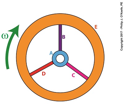
We learned in a previous blog that torque is most simply defined as a measure of how much force acts upon an object to cause it to rotate around a pivot point or center of rotation, shown as a small black dot in the illustration. For our discussion we’ll focus on two parts of the flywheel, the hub, part A, and the rim, part E.
Part A has a mass mA located a distance rA from the flywheel’s center, while part E has a mass mE located a distance rE from it. When an engine applies mechanical power to the flywheel by way of its rotating shaft, the revolutions per minute, RPM, increase and along with it the angular velocity, ω, also increases. For a refresher on this, follow the link.
Because of this relationship, we can calculate the kinetic energy contained within a flywheel using the kinetic energy formula,
KE = ½ × ∑[m × r2] × ω2 (1)
As the flywheel’s angular velocity increases or decreases in response to the engine’s energy output, parts A and E reflect acceleration or deceleration of aA and aE. Since parts A and E exhibit both mass and acceleration, they are subject to Newton’s Second Law of Motion, which states that force equals mass times acceleration. Using that relationship we can calculate the force exerted on each part by,
FA = mA × aA (2)
FE = mE × aE (3)
Part A is small compared to part E, therefore mE is greater than mA and accordingly FE is greater than FA. Forces FA and FE act as torques, because they cause parts A and E to rotate around the flywheel’s center of rotation, so they are designated as Torque A, TA, and Torque E, TE. These torques are computed by,
TA = FA × rA (4)
TE = FE × rE (5)
Part E’s greater mass will contribute more torque than part A, and it will also contribute more to the flywheel’s kinetic energy content.
Most flywheels are designed with heavy rims supported by small hubs and slender spokes, because the more mass that’s distributed away from the flywheel’s center of rotation, the greater the flywheel’s moment of inertia and torque, and the more kinetic energy it can store.
Next time we’ll develop an equation which allows us to quantify the horsepower required to accelerate a flywheel.
opyright 2017 – Philip J. O’Keefe, PE
Engineering Expert Witness Blog
____________________________________ |
Tags: distribution of mass, engineering, flywheel, kinetic energy, mass, moment of inertia, torque
Posted in Engineering and Science, Expert Witness, Forensic Engineering, Innovation and Intellectual Property, Personal Injury, Product Liability | Comments Off on Flywheel Torque and Distribution of Mass
Monday, November 6th, 2017
|
Last time we arrived at a general formula to compute the kinetic energy, KE, contained within the totality of a spinning flywheel made up of numerous parts. Today we’ll discuss the terms in that formula, which encompasses a phenomenon of flywheels known as moment of inertia.
Moment of Inertia in a Flywheel
The kinetic energy formula we’ve been working with is, again,
KE = ½ × Σ[m × r2] × ω2 (1)
The bracketed part of this equation makes reference to spinning flywheels comprised of one or more parts, and that’s what we’ll be focusing on today. The symbol Σ is the Greek letter sigma, standard engineering shorthand notation used to represent the sum of all terms and mathematical operations contained within the brackets.
Our illustration shows we have five parts to consider: a hub, three spokes and a rim, and label them A, B, C, D, and E respectively. Each part has its own mass, m, and is a unique distance, r, from the flywheel’s center of rotation. The flywheel’s angular velocity is represented by ω.
For our flywheel of parts A through E our expanded equation becomes,
Σ[m × r2] = [mA × rA2] + [mB × rB2] + [mC × rC2] + [mD × rD2] + [mE × rE2] (2)
Equation (2) represents the sum total of moments of inertia contained within our flywheel. It’s a numerical representation of the flywheel’s degree of resistance to changes in motion.
The more mass a flywheel has, the greater its moment of inertia. When at rest this greater moment of inertia means it will take more effort to return it to motion. But once in motion the flywheel’s greater moment of inertia will make it harder to stop. That’s because there’s a lot of kinetic energy stored within its spinning mass, and the heavier a flywheel is, the more kinetic energy it contains. In fact, for any given angular velocity ω, a large and heavy flywheel stores more kinetic energy than a smaller, lighter flywheel.
But there’s more to a flywheel’s moment of inertia than just mass. What’s really important is how that mass is distributed. We’ll get into that next time when we discuss torque.
Copyright 2017 – Philip J. O’Keefe, PE
Engineering Expert Witness Blog
____________________________________ |
Tags: angular velocity, center of rotation, engineering, flywheel, kinetic energy storage, mass, moment of inertia, spinning flywheel
Posted in Engineering and Science, Expert Witness, Forensic Engineering, Innovation and Intellectual Property, Personal Injury, Product Liability | Comments Off on Moment of Inertia in a Flywheel
Thursday, October 26th, 2017
|
Last time we introduced the fact that spinning flywheels are subject to both linear and angular velocities, along with a formula that allows us to calculate these quantities for a single part of the flywheel, designated A. We also re-visited the kinetic energy formula. Today we’ll build upon those formulas as we attempt to answer the question, How much kinetic energy is contained within a spinning flywheel?
Here again is the basic kinetic energy formula,
KE = ½ × m × v2 (1)
where, m equals a moving object’s mass and v is its linear velocity.
Here again is the formula used to calculate linear and angular velocities for a single part A within the flywheel, where part A’s linear velocity is designated vA, angular velocity by ω, and where rA is the distance of part A from the flywheel’s center of rotation.
vA = rA × ω (2)
Working with these two formulas, we’ll insert equation (2) into equation (1) to obtain a kinetic energy formula which allows us to calculate the amount of energy contained in part A of the flywheel,
KEA = ½ × mA × (rA × ω)2 (3)
which simplifies to,
KEA = ½ × mA × rA2 × ω2 (4)
Equation (4) is a great place to begin to calculate the amount of kinetic energy contained within a spinning flywheel, however it is just a beginning, because a flywheel contains many parts. Each of those parts has its own mass, m, and is a unique distance, r, from the flywheel’s center of rotation, and all these parts must be accounted for in order to arrive at a calculation for the total amount of kinetic energy contained within a spinning flywheel.
How Much Kinetic Energy is Contained Within a Spinning Flywheel?
Put another way, we must add together all the m × r2 terms for each and every part of the entire flywheel. How many parts are we speaking of? Well, that depends on the type of flywheel. We’ll discuss that in detail later, after we define a phenomenon that influences the kinetic energy of a flywheel known as the moment of inertia.
For now, let’s just consider the flywheel’s parts in general terms. A general formula to compute the kinetic energy contained within the totality of a spinning flywheel is,
KE = ½ × ∑[m × r2] × ω2 (5)
We’ll discuss the significance of each of these variables next time when we arrive at a method to calculate the kinetic energy contained within all the many parts of a spinning flywheel
.
Copyright 2017 – Philip J. O’Keefe, PE
Engineering Expert Witness Blog
____________________________________ |
Tags: angular velocity, center of rotation, engineering, flywheel, kinetic energy, linear velocity, mass, moment of inertia
Posted in Engineering and Science, Expert Witness, Forensic Engineering, Innovation and Intellectual Property, Personal Injury, Product Liability, Professional Malpractice | Comments Off on How Much Kinetic Energy is Contained Within a Spinning Flywheel?
Thursday, October 19th, 2017
|
Anyone who has spun a potter’s wheel is appreciative of the smooth motion of the flywheel upon which they form their clay, for without it the bowl they’re forming would display irregularities such as unattractive bumps. The flywheel’s smooth action comes as a result of kinetic energy, the energy of motion, stored within it. We’ll take another step towards examining this phenomenon today when we take our first look at calculating this kinetic energy. To do so we’ll make reference to the two types of velocity associated with a spinning flywheel, angular velocity and linear velocity, both of which engineers must negotiate anytime they deal with rotating objects.
Let’s begin by referring back to the formula for calculating kinetic energy, KE. This formula applies to all objects moving in a linear fashion, that is to say, traveling a straight path. Here it is again,
KE = ½ × m × v2
where m is the moving object’s mass and v its linear velocity.
Flywheels rotate about a fixed point rather than move in a straight line, but determining the amount of kinetic energy stored within a spinning flywheel involves an examination of both its angular velocity and linear velocity. In fact, the amount of kinetic energy stored within it depends on how fast it rotates.
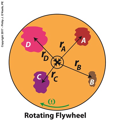
For our example we’ll consider a spinning flywheel, which is basically a solid disc. For our illustrative purposes we’ll divide this disc into hypothetical parts, each having a mass m located a distance r from the flywheel’s center of rotation. We’ll select a single part to examine and call that A.
Two Types of Velocity Associated With a Spinning Flywheel
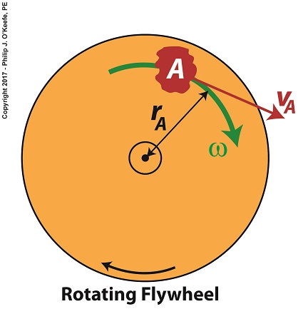
Part A has a mass, mA, and is located a distance rA from the flywheel’s center of rotation. As the flywheel spins, part A rides along with it at an angular velocity, ω, following a circular path, shown in green. It also moves at a linear velocity, vA, shown in red. vA represents the linear velocity of part A measured at any point tangent to its circular path. This linear velocity would become evident if part A were to become disengaged from the flywheel and cast into the air, whereupon its trajectory would follow a straight line tangent to its circular path.
The linear and angular velocities of part A are related by the formula,
vA = rA × ω
Next time we’ll use this equation to modify the basic kinetic energy formula so that it’s placed into terms that relate to a flywheel’s angular velocity. This will allow us to define a phenomenon at play in the flywheel’s rotation, known as the moment of inertia.
Copyright 2017 – Philip J. O’Keefe, PE
Engineering Expert Witness Blog
____________________________________ |
Tags: angular velocity, energy stored, engineering, flywheel, kinetic energy, linear velocity, mass, moment of inertia, spinning flywheel
Posted in Engineering and Science, Expert Witness, Forensic Engineering, Innovation and Intellectual Property, Personal Injury, Product Liability, Professional Malpractice | Comments Off on Two Types of Velocity Associated With a Spinning Flywheel
Monday, June 6th, 2016
|
As an engineering expert, I often use the fact that formulas share a single common factor in order to set them equal to each other, which enables me to solve for a variable contained within one of them. Using this approach we’ll calculate the velocity, or speed, at which the broken bit of ceramic from the coffee mug we’ve been following slides across the floor until it’s finally brought to a stop by friction between it and the floor. We’ll do so by combining two equations which each solve for kinetic energy in their own way.
Last time we used this formula to calculate the kinetic energy, KE, contained within the piece,
KE = FF × d (1)
and we found that it stopped its movement across the floor when it had traveled a distance, d, of 2 meters.
We also solved for the frictional force, FF, which hampered its free travel, and found that quantity to be 0.35 kilogram-meters/second2. Thus the kinetic energy contained within that piece was calculated to be 0.70 kilogram-meters2/second2.
Now we’ll put a second equation into play. It, too, provides a way to solve for kinetic energy, but using different variables. It’s the version of the formula that contains the variable we seek to calculate, v, for velocity. If you’ll recall from a previous blog, that equation is,
KE = ½ × m × v2 (2)
Of the variables present in this formula, we know the mass, m, of the piece is equal to 0.09 kilograms. Knowing this quantity and the value derived for KE from formula (1), we’ll substitute known values into formula (2) and solve for v, the velocity, or traveling speed, of the piece at the beginning of its slide.

Combining Kinetic Energy Formulas to Calculate Velocity
The ceramic piece’s velocity is thus calculated to be,
KE = ½ × m × v2
0.70 kilogram-meters2/second2= ½ × (0.09 kilograms) × v2
now we’ll use algebra to rearrange things and isolate v to solve for it,
v2 = 2 × (0.70 kilogram-meters2/second2) ÷ (0.09 kilograms)
v = 3.94 meters/second =12.92 feet/second = 8.81 miles per hour
Our mug piece therefore began its slide across the floor at about the speed of an experienced jogger.

This ends our series on the interrelationship of energy and work. Next time we’ll begin a new topic, namely, how pulleys make the work of lifting objects and driving machines easier.
Copyright 2016 – Philip J. O’Keefe, PE
Engineering Expert Witness Blog
____________________________________ |
Tags: distance, energy, engineering expert, friction, frictional force, kinetic energy, mass, velocity, work
Posted in Engineering and Science, Expert Witness, Forensic Engineering, Innovation and Intellectual Property, Personal Injury, Product Liability | Comments Off on Combining Kinetic Energy Formulas to Calculate Velocity
Wednesday, May 25th, 2016
|
My activities as an engineering expert often involve creative problem solving of the sort we did in last week’s blog when we explored the interplay between work and kinetic energy. We used the Work-Energy Theorem to mathematically relate the kinetic energy in a piece of ceramic to the work performed by the friction that’s produced when it skids across a concrete floor. A new formula was derived which enables us to calculate the kinetic energy contained within the piece at the start of its slide by means of the work of friction. We’ll crunch numbers today to determine that quantity.
The formula we derived last time and that we’ll be working with today is,
 Calculating Kinetic Energy By Means of the Work of Friction
where, KE is the ceramic piece’s kinetic energy, FF is the frictional force opposing its movement across the floor, and d is the distance it travels before friction between it and the less than glass-smooth floor brings it to a stop.
The numbers we’ll need to work the equation have been derived in previous blogs. We calculated the frictional force, FF, acting against a ceramic piece weighing 0.09 kilograms to be 0.35 kilogram-meters/second2 and the measured distance, d, it travels across the floor to be equal to 2 meters. Plugging in these values, we derive the following working equation,
KE = 0.35 kilogram-meters/second2 × 2 meters
KE = 0.70 kilogram-meters2/second2
The kinetic energy contained within that broken bit of ceramic is just about what it takes to light a 1 watt flashlight bulb for almost one second!
Now that we’ve determined this quantity, other energy quantities can also be calculated, like the velocity of the ceramic piece when it began its slide. We’ll do that next time.
Copyright 2016 – Philip J. O’Keefe, PE
Engineering Expert Witness Blog
____________________________________ |
Tags: distance, electrical energy, energy, engineering expert, frictional force, kinetic energy, mass, velocity, Watt, work, work of friction, work-energy theorem
Posted in Engineering and Science, Expert Witness, Forensic Engineering, Innovation and Intellectual Property, Personal Injury, Product Liability | Comments Off on Calculating Kinetic Energy By Means of the Work of Friction
Thursday, May 12th, 2016
|
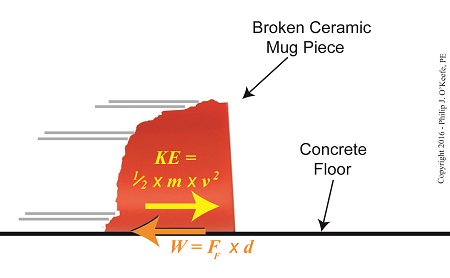
We’ve been discussing the different forms energy takes, delving deeply into de Coriolis’ claim that energy doesn’t ever die or disappear, it simply changes forms depending on the tasks it’s performing. Today we’ll combine mathematical formulas to derive an equation specific to our needs, an activity my work as an engineering expert frequently requires of me. Our task today is to find a means to calculate the amount of kinetic energy contained within a piece of ceramic skidding across a concrete floor. To do so we’ll combine the frictional force and Work-Energy Theorem formulas to observe the interplay between work and kinetic energy.
As we learned studying the math behind the Work-Energy Theorem, it takes work to slow a moving object. Work is present in our example due to the friction that’s created when the broken piece moves across the floor. The formula to calculate the amount of work being performed in this situation is written as,
W = FF ×d (1)
where, d is the distance the piece travels before it stops, and FF is the frictional force that stops it.
We established last time that our ceramic piece has a mass of 0.09 kilograms and the friction created between it and the floor was calculated to be 0.35 kilogram-meters/second2. We’ll use this information to calculate the amount of kinetic energy it contains. Here again is the kinetic energy formula, as presented previously,
KE = ½ × m × v2 (2)
where m represents the broken piece’s mass and v its velocity when it first begins to move across the floor.
The Interplay of Work and Kinetic Energy
The Work-Energy Theorem states that the work, W, required to stop the piece’s travel is equal to its kinetic energy, KE, while in motion. This relationship is expressed as,
KE = W (3)
Substituting terms from equation (1) into equation (3), we derive a formula that allows us to calculate the kinetic energy of our broken piece if we know the frictional force, FF, acting upon it which causes it to stop within a distance, d,
KE = FF × d
Next time we’ll use this newly derived formula, and the value we found for FF in our previous article, to crunch numbers and calculate the exact amount of kinetic energy contained with our ceramic piece.
Copyright 2016 – Philip J. O’Keefe, PE
Engineering Expert Witness Blog
____________________________________ |
Tags: distance, energy, engineering expert, frictional force, kinetic energy, mass, velocity, work, work-energy theorem
Posted in Engineering and Science, Expert Witness, Forensic Engineering, Innovation and Intellectual Property, Personal Injury, Product Liability | Comments Off on The Interplay of Work and Kinetic Energy
Thursday, April 14th, 2016
|
Last time we introduced the force of friction, another force in our ongoing discussion about changing forms of energy, and we learned that it’s often a counterproductive force which design engineers and engineering experts such as myself must work to minimize in order to optimize functionality of devices we’re designing. Today we’ll introduce the frictional force formula, which computes the amount of friction present when two surfaces meet.
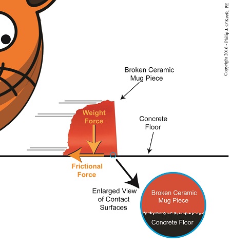
To demonstrate frictional force, we’ve been working with the example of a shattered mug’s broken ceramic pieces and watching their progress as they slide across a concrete floor. They eventually come to a stop not too far from the point where the mug shattered, because friction causes them to stop. The mass of the ceramic pieces in combination with the downward pull of gravity causes the broken bits to “bear down” on the floor, thereby maximizing contact and creating friction.
At first glance the floor and mugs’ surfaces may appear slippery smooth, but when viewed under magnification we see that both actually contain many peaks and valleys. The peaks of one surface project into the valleys of the other and it’s fight, fight, fight for the ceramic pieces to continue their progress across the floor. The strength of the frictional force acting upon the pieces is a factor of their individual weights coupled with the roughness of the two surfaces coming into contact — the shattered pieces and the floor. If friction didn’t exist and no other impediments were in the way, the pieces might travel to the next state before stopping!
Frictional Force Resists Motion
Last time we introduced Charles-Augustin de Coulomb, a scientist whose work with friction led to the later development of a formula to calculate it. It’s presented here, and frictional force is denoted as FF,
FF = μ × m × g
where, m is the mass of an object making contact with another surface and g is the gravitational acceleration constant, which is due to the force of Earth’s gravity. The Greek letter μ, pronounced “mew,” represents the coefficient of friction, a number. Numerical values for μ were determined by laboratory testing and are recorded in engineering books for many combinations of materials, including rubber on concrete, leather on steel, wood on aluminum, and our own example of ceramic on concrete.
Next time we’ll plug the numbers that apply to our ceramic-on-concrete example into the friction formula and calculate the frictional force at play.
Copyright 2016 – Philip J. O’Keefe, PE
Engineering Expert Witness Blog
____________________________________ |
Tags: Charles-Augustin de Coulomb, coefficient of friction, Earth's gravity, energy, engineering expert, friction, friction force formula, frictional force, gravitational acceleration constant, mass, mu
Posted in Engineering and Science, Expert Witness, Forensic Engineering, Innovation and Intellectual Property, Personal Injury, Product Liability | Comments Off on The Frictional Force Formula
Thursday, March 24th, 2016
|
Last time we watched our example ceramic coffee mug crash to a concrete floor, where its freefall kinetic energy performed the work of shattering it upon impact. This is a scenario familiar to engineering experts like myself who are sometimes asked to reconstruct accidents and their aftermaths, otherwise known as forensic engineering. Today we’ll take a look at what happens when the shattered mug’s pieces are freed from their formerly cozy, cohesive bond, and we’ll watch their transmutation from kinetic energy to work, and back to kinetic energy.
As we watch our mug shatter on the floor, we notice that it breaks into different sized pieces that are broadcast in many directions around the point of impact. Each piece has its own unique mass, m, travels at its own unique velocity, v, and has a unique and individualized amount of kinetic energy. This is in accordance with the kinetic energy formula, shown here again:
KE = ½ × m × v2
So where did that energy come from?

The Scattering Pieces Have Kinetic Energy
According to the Work-Energy Theorem, the shattered mug’s freefalling kinetic energy is transformed into the work that shatters the mug. Once shattered, that work is transformed back into kinetic energy, the energy that fuels each piece as it skids across the floor.
The pieces spray out from the point of the mug’s impact until they eventually come to rest nearby. They succeed in traveling a fair distance, but eventually their kinetic energy is dissipated due to frictional force which slows and eventually stops them.
The frictional force acting in opposition to the ceramic pieces’ travel is created when the weight of each fragment makes contact with the concrete floor’s rough surface, which creates a bumpy ride. The larger the fragment, the more heavily it bears down on the concrete and the greater the frictional force working against it. With this dynamic at play we see smaller, lighter fragments of broken ceramic cover a greater distance than their heavier counterparts.
The Work-Energy Theorem holds that the kinetic energy of each piece equals the work of the frictional force acting against it to bring it to a stop. We’ll talk more about this frictional force and its impact on the broken pieces’ distance traveled next time.
Copyright 2016 – Philip J. O’Keefe, PE
Engineering Expert Witness Blog
____________________________________ |
Tags: engineering expert, force, forensic engineering, friction force, kinetic energy, kinetic energy formula, mass, velocity, work, work-energy theorem
Posted in Engineering and Science, Expert Witness, Forensic Engineering, Innovation and Intellectual Property, Personal Injury, Product Liability | Comments Off on Kinetic Energy to Work, Work to Kinetic Energy


