| Whether or not you live or work in a city, you are probably aware of rush hour traffic and how frustrating it can be. As a matter of fact, this traffic is the number one reason many choose to live within cities providing public transportation. Instead of watching the cars pile up in front of you, you can be checking your email or reading the paper. And no matter where you live, you’ve probably encountered a narrow one-lane road at some time. If this road were to be spotted with traffic lights and double parked cars, the resulting frustration would reach a new high, one which has you craving the freedom of a crowded three-lane expressway. At least there’s the possibility of movement there.
Generally, the wider the road and the fewer the impediments, the better traffic will flow. The problems presented by vehicular traffic are analogous to those present in electrical wires. For both, obstructions are impediments to flow. You see, the thicker the metal is in a wire, the more electrical current it can carry. But before we explore why, let’s see how electric wires are classified. If you’ve ever spent any time hanging around a hardware store looking at the goodies, you’ve probably come across wire gauge numbers, used to categorize wire diameter. American Wire Gauge (AWG) is a standardized wire gauge system, used in North American industry since the latter half of the 19th Century. Handy as it is, the AWG gauge numbering system seems to go against logic, because as a wire’s diameter increases, its gauge number decreases. For example, a wire gauge number of 8 AWG has a diameter of 0.125 inches, while a gauge number of 12 AWG has a diameter of 0.081 inches. To make things easier on those who need to know this type of information, wire diameter is tabulated for each AWG gauge number and readily available in engineering reference books. So what does this have to do with electric current? To begin with, the larger the AWG number, the less current it can safely carry. If we turn to an engineering reference book, and look up information relating to an 8 AWG insulated copper wire, we find that it can safely carry an electrical current of 50 amperes, while a 12 AWG insulated copper wire can safely carry only 25 amperes. This information allows us to make important and relevant design decisions regarding a myriad of things, from electrical wiring in electronic devices, to appliances, automobiles, and buildings. So, why are bigger wires able to carry more current? Well, as you’ve heard me say before, no wire is a perfect conductor of electricity, but some metals, take copper for instance, are better conductors than others, say steel. But even the best conductors are inherently full of impurities and imperfections that resist the flow of electricity. This electrical resistance acts much like traffic lights and double parked cars that impede the flow of traffic. The larger the diameter of the wire, the less electrical resistance is present. The logic here is simple. Wire that is larger allows more paths for electrical current to flow around impurities and imperfections. The congestion present in rush hour traffic results in travel delays and hot tempers, and heat is also present in electric wires that face resistance to electricity flow. If the resistance to electric current flow is high enough, it can cause overheating. Road rage within the wires is a possibility, and if the wires get hot enough, electrical insulation can melt and burn, creating a fire. Known as the “Joule heating” effect, this phenomenon is responsible for its share of building fires. We’ll learn more about Joule heating and how wires are sized to keep electrical current flow within safe limits next week. Until then, try to keep out of traffic. _____________________________________________
|
Archive for the ‘Professional Malpractice’ Category
Wire Size and Electric Current
Sunday, March 13th, 2011
Coal Power Plant Fundamentals – “Big Coal”
Sunday, February 27th, 2011|
We’ve been talking about coal fired power plants for some time now, and it’s always good to introduce third party information on subject matter in order to gain the most from the discussion. What follows is an excerpt of an interesting book review on the subject of coal consumption which appeared in the New York Times: There is perhaps no greater act of denial in modern life than sticking a plug into an electric outlet. No thinking person can eat a hamburger without knowing it was once a cow, or drink water from the tap without recognizing, at least dimly, that its journey began in some distant reservoir. Electricity is different. Fully sanitized of any hint of its origins, it pours out of the socket almost like magic. In his new book, Jeff Goodell breaks the spell with a single number: 20. That’s how many pounds of coal each person in the United States consumes, on average, every day to keep the electricity flowing. Despite its outdated image, coal generates half of our electricity, far more than any other source. Demand keeps rising, thanks in part to our appetite for new electronic gadgets and appliances; with nuclear power on hold and natural gas supplies tightening, coal’s importance is only going to increase. As Goodell puts it, “our shiny white iPod economy is propped up by dirty black rocks.” To read the entire article, follow this link: http://www.nytimes.com/2006/06/25/books/review/25powell.html?_r=2
A locomotive crane unloading coal from railcars at a power plant in the late 1930s. Next week we’ll continue our regular series, following energy’s journey through the power plant. _____________________________________________ |

Coal Power Plant Fundamentals
Sunday, January 23rd, 2011| Several years ago I was asked by power producers within the electric utility industry to write and then present a training course on the subject of coal power plant fundamentals. The finished product was a two day introductory course on the energy transformation process within a coal fired plant.
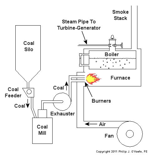
Since that time my seminar, entitled Coal Power Plant Fundamentals, has been presented to a variety of audiences, including Mirant Corporation, Platte River Power Authority, and Integrys Energy Group, Inc. Audience makeup has been diverse and has included equipment manufacturers, mining companies, power industry consultants, and regulatory agencies. This seminar, which I continue to present today in meeting rooms across the country, covers all major systems in a typical power plant, from coal handling when the coal first enters the plant, to its eventual end destination, the electrical switch yard which facilitates power transmission to customers. My Power Point presentation is embellished with ample illustrations, including photographs that I have taken during the course of my career and diagrams which I created using CAD, or Computer Aided Drawing software, one of which is featured below. In addition to the overhead slides, I provide a 150-page bound book which is distributed to seminar attendees. They use it to both follow along with my lecture and have a source of refresher material to take home with them. I’ve been told that having my illustrations in front of them makes a world of difference towards their understanding of the subject matter. The unique thing about my course is that it focuses on the simplified presentation of complex engineering concepts, much like my blogs do. Of course it always helps to have an engineering background or scientific background of sorts, but I wrote the course to accommodate understanding of the subject matter by individuals without any technical background. Accountants, salespersons, administrative staff, plant operating and maintenance workers, and journalists have all found the course to be easy to follow, interesting, and informative. So how do you get electricity from coal? To answer this question and give you a sampling of my seminar material let’s take a look at Figure 1.
Figure 1 – The Coal Power Plant Energy Transformation Process Following along from left to right, the coal is first burned in order to transform the chemical energy which it contains into heat energy. That heat energy is then absorbed by water inside a nearby boiler, where it is converted into steam. The heat energy in the steam flows through a pipe into a steam turbine where it is again transformed, this time into mechanical energy that enables the turbine shaft to spin. The mechanical energy in the turbine is then transmitted by its shaft, enabling it to turn an electrical generator. And, finally, the mechanical energy is transformed by the generator into electrical energy for our usage. Simple process, right? Well, maybe, maybe not. My illustration certainly helped to simplify things, but there are a lot of details that were purposely omitted so as not to “muddy the waters.” It’s those details which have the potential to make things a lot more complicated, and next week we’ll begin to take a closer look at some of them. _____________________________________________
|


Sound and Its Control
Sunday, November 21st, 2010| How do they do it? Your teenager is busily doing his homework, the sound on their stereo speakers cranked up way past the point of your comfort. As the heavy bass beats against your eardrums, their sound waves continue to travel throughout the house, crashing into walls and uprooting small objects from their positions on shelves. Thankfully, controlling this uncomfortable sound level is relatively easy, as you scream out, “Turn that music down!”
Many dangerously loud sounds are not so easily controlled, as when they take place in industrial settings. Here, when complex machinery and manufacturing processes are at full tilt, one can’t just turn a single knob or pull a plug to gain relief. Controlling sound levels in factories, power plants, and construction sites is often a complex task, relegated to engineers with state of the art equipment meant to measure and assess sound exposures in order to devise a strategy to control them. Let’s take a look at a few of these control methods. For our example, we’ll consider the challenge faced by a fictitious company, Widget USA. Business has picked up, and they need to install an additional manufacturing line in their factory. Now widget manufacturing machinery is notoriously noisy, and management is thinking ahead about protecting widget line workers from potentially dangerous sound levels. Their manufacturing engineers dutifully keep this in mind while devising their requirements specification, a list of “must haves” routinely included in quotation requests to potential manufacturers bidding on the job. Of utmost concern is to limit the number of decibels (dB) that the new widget machine can produce. If a manufacturer under consideration is unable to meet these requirements, Widget USA will take their business elsewhere. This methodology essentially nips the excessive noise problem in the bud, eliminating the noise source before it is introduced into the factory, and this is by far the best way of dealing with our scenario. Well suppose things aren’t as neat for Widget USA. Their factory contains many existing manufacturing lines with old, noisy machines. Sure, they’d like to replace them with newer, quieter ones, but there’s a problem, and it’s one all-too familiar to most companies: the expense involved. How can they most effectively deal with this situation? Perhaps Widget USA can modify their existing machinery, or perhaps their overall noise reduction objectives can be achieved by simply replacing worn parts that have a tendency to vibrate. If this measure isn’t sufficient, perhaps sound barriers can be introduced. Whether these are installed around entire machines or parts thereof, they are often effective at absorbing excessive noise. Barriers such as these are made of materials like plastic foam and mass loaded vinyl (MLV) which serve to muffle sound waves. Yet another approach to noise containment is to provide workers in the vicinity of the machinery with sound-absorbing personal safety equipment, ear plugs and the like. If the noise present is loud enough, perhaps a wall, reminiscent of the type often built along stretches of populated highway can be erected. Yet another way to deal with undesirable sound levels is to divert the noise to a location not normally occupied by humans. This is the tact often taken with industrial boilers. Their highly pressurized steam expands so rapidly it can create a deafening roar, and engineers often design piping systems which stem from the safety valve on the boilers themselves up to the roof of the building housing them. In this way the steam and its accompanying noise is safely redirected outside, where only the birds passing overhead will be bothered by it. This wraps up our discussion on sound, its measurement and containment. Perhaps you’ve learned a trick or two to help alleviated unwanted sounds in your environment, whether it’s produced by your teen or your neighbor’s leaf blower. _____________________________________________
|

Pressurized Containers – ASME Boiler and Pressure Vessel Code
Sunday, October 24th, 2010| Over the last few weeks we looked at the dangers associated with pressurized containers, also known as “pressure vessels.” We also looked at overpressure devices that can keep the pressure from building to the point where the vessel ruptures. But what about keeping pressure vessels from rupturing under normal operating pressure? You know, pressures well below the point where an overpressure device would kick in. This can happen if there is some sort of weakness in the pressure vessel caused by things like poor design, defective materials, or bad welds.
In the 19th Century the machines of the Industrial Revolution were driven by steam. Those magnificent machines advanced our civilization and standard of living. Sounds like a win-win situation, right? Wrong! The downside was that there were no standards for the design of pressure vessels like air storage tanks and boilers. Every engineer had their own ideas as to how they wanted to approach pressure vessel design. I use the word “engineer” loosely because most “engineers” of that time were not college graduates. Some approaches were good, some were bad, and some were in between. The end result was often not good. There were many pressure vessel leaks and explosions that damaged property, caused injury, and took lives. By the turn of the 20th Century industrialization spread far and wide, intensifying safety concerns about pressure vessels. One deadly incident was the straw that broke the camel’s back. On March 10, 1905, the boiler failed in a shoe factory in Brockton, Massachusetts. 58 people were killed and another 117 were injured. The factory was completely destroyed. This tragedy prompted Massachusetts to form a Board of Boiler Rules to write boiler laws. Ohio followed with their own boiler laws. This was a step in the right direction, but each state law was different and a boiler that was legal in one state was illegal in another. There was no standardization between states. In 1911 the American Society of Mechanical Engineers (ASME) formed its Boiler and Pressure Vessel Committee to address the lack of standardization. The committee’s work resulted in publication of the Boiler and Pressure Vessel Code (BPVC). In a nutshell, the BPVC establishes standardized rules governing the design, fabrication, testing, inspection, and repair of boilers and other pressurized vessels and containers. The BPVC set the standards that can be adopted by all states to minimize risk to the public. The ASME is not a government agency, so it cannot enforce compliance with the BPVC. As a matter of fact, compliance with the BPVC by manufacturers has been completely voluntary. However, most state laws now require that pressure vessels must be certified by their manufacturers to be in compliance with the BPVC before they can be sold and put into operation. A certified pressure vessel must be permanently and conspicuously marked with the manufacturer’s name, the date built, serial number, and information about its construction and the type of use it’s designed for. That wraps it up for our series about pressurized containers. Next time, we’ll shift gears and take a look at the project triangle and how it influences the outcome of engineering designs. _____________________________________________
|

Pressurized Containers – Industrial Overpressure Devices
Sunday, October 17th, 2010| Perhaps you went out on a drive to enjoy a nice summer day. As you ventured into uncharted territory, you might have ended up in an industrial area. There, you noticed factories, chemical plants, and oil refinery complexes, each surrounded by a huge system of pipes and tanks. You might have considered it to be an eyesore, but if you’re an artist and engineer like I am, you might look at it as a form of art, composed of interesting shapes, colors, and patterns. No matter how you look at it, you can bet that there are at least a few pressurized containers in there.
Last time we saw how something as seemingly harmless as a home water heater could become a dangerous missile if the pressure inside builds to the point where the tank ruptures. You can imagine what kind of explosive forces, steam, and chemicals would be unleashed into the surroundings if an industrial sized pressurized container failed due to overpressure. Let’s explore some other types of overpressure devices that are commonly used in industrial settings. One type of overpressure device is a safety valve. They are similar to a water heater relief valve, but they are generally used to relieve overpressure of gases and steam. How do they work? Basically, a safety valve is attached to the top of a pressurized container as shown in the cut away view in Figure 1 below.
Figure 1 – A Basic Safety Valve In The Closed Position A powerful spring in the valve body is designed to force down on the valve and keep it closed if there is normal pressure inside the container. Once the pressure begins to rise to an unsafe level, it pushes up against the valve and overcomes the force of the spring. The valve opens, as shown in Figure 2 below, and the contents of the pressurized container are safely vented out to an area that is normally unoccupied by people. In case you’re wondering, safety valves are commonly used on pressurized storage tanks and boilers.
Figure 2 – A Basic Safety Valve In The Open Position Another way to address the overpressure scenario is to employ a rupture disc. This is in fact a purposely constructed weak spot. It is intentionally built into a pressurized container and is designed so that it will fail when pressure starts to rise. In fact, this disc is designed to fail at a pressure point just below the pressure at which the container itself would fail. The disc is usually located within a vent pipe, which is in turn connected to the container. Should the disc rupture in an overpressure situation, the contents of the pressurized container will safely flow out of the vent pipe to a place normally unoccupied by people. The advantage of using a rupture disc is that they are made to safely release huge quantities of pressurized substances very quickly. The disadvantage in their usage is that they’re a one-time fix. That is, unlike relief or safety valves which may perform their function a multitude of times, a rupture disc is destroyed once it does its job. They are generally used in industrial settings where potential hazards are greater than at home, so once the rupture disc blows, the complete system generally undergoes a shut down so that the disc an be replaced before the pressurized container can be used again. Another option to pressure containment is the use of a fusible plug, usually constructed of a metal that will melt if the temperature within a pressurized container rises above a certain level. The metal plug melts, and excess pressure is vented through the aperture formed into a safe location. These are often used on locomotive boilers and compressed gas cylinders. Like rupture discs, fusible plugs are a one-time fix and must be replaced once they have done their job. Yet another option to pressure containment is to use a temperature limiting control. This category includes devices that monitor temperature and pressure within a pressurized container. If a dangerous situation should develop, the control system reacts, effectively reducing the pressure to prevent failure of the vessel. Automatic combustion control systems for boilers in electric utility power plants use temperature and pressure sensors to keep pressures within safe limits by regulating fuel and air input to the boiler. Next time we’ll cover the American Society of Mechanical Engineers (ASME) Boiler and Pressure Vessel Code (BPVC), which establishes rules governing the design, fabrication, testing, inspection, and repair of boilers and other pressurized containers. _____________________________________________ |


Pressurized Containers – Overpressure Devices
Sunday, October 10th, 2010| Have you ever come home to a basement full of water? The sinking feeling in your stomach at the moment of discovery is soon followed by a cascade of other emotions: fear, anger, and you probably had a few choice sailor’s words to round off the experience.
What’s just happened? Well, it may very well have been a water heater explosion, and the water on the floor may be just the beginning of the damage. Perhaps you even have a hole blown into the side of your house! Watch this video for excellent graphic footage of just such an explosion: You probably didn’t realize that the water heater in your home has the potential to become a pressure vessel, and with that present all of the potential dangers that a pressure vessel presents. Remember our discussion on the Boyle-Charles Law a few weeks ago? We learned that in the fixed volume environment of a pressurized container if the temperature keeps climbing, the pressure keeps building, and the outcome of this coupling is precisely what we’re observing in the video. The water in the water heater has turned to steam, causing pressure to build in the vessel until rupture occurs. None of us wants to come home to a basement filled with water, much less a hole blown through our house by a rocketing water heater, so how can we prevent it from happening? One answer is to have your water heater regularly serviced by a qualified plumber. The plumber would make sure that the overpressure device on the water heater tank, namely the relief valve (a.k.a. T&P valve), is in proper working order. Now you may have noticed a circle drawn around the water heater’s relief valve in the video. As their name implies, relief valves are used to relieve pressure buildup, generally of liquids. If the pressure within the water heater reaches a certain limit, set by the heater’s manufacturer, the relief valve will automatically open to vent off the pressure. A pipe on the outlet of the valve safely directs the water and steam that is let off to the floor where it can flow down to a drain. That’s why floor drains are usually located in close proximity to water heaters. Besides relief valves, overpressure devices come in many configurations, including: safety valves, rupture discs, fusible plugs, and temperature limiting controls. They may be used singly or jointly in order to perform the same basic function, that is, to keep the pressure within a vessel from building to the point where it may fail. Next week we’ll explore the other overpressure devices mentioned and where they are generally employed. _____________________________________________
|

Pressurized Containers
Sunday, September 19th, 2010| My dear daughter is at times forgetful? On one occasion in particular she forgot that she had placed a can of pop in the freezer to speed-chill it. Later that evening when my wife went to get something out of the freezer she was not too pleasantly surprised to find that a black, semi-solid mess had covered most of the freezer’s interior. You got it. The pop can exploded, shooting its pressurized contents all over the place.
You may not have thought much about it before, but pressurized containers are all around us, from pop to aerosol cans, car tires, water heaters, and liquid petroleum gas tanks. Pressurized containers are even more obvious in industrial settings such as oil refineries, power plants, and factories. As its name would imply, pressurized containers, or pressure vessels, are under a lot of pressure, as such, they are no stronger than their weakest point. Whether that point be its sides, as in the case of my daughter’s ruptured pop can, or its ends, weld joints, rivets, or any of the other components that are included in the vessel’s construction. As with anything, the integrity of something is only as good as its weakest part. In an industrial setting, this fact, depending on the vessel’s contents and the severity of the failure, can prove deadly. So what causes pressure in a vessel to get too high? Many factors could be at play, from a safety valve which fails to do its job of relieving excess pressure, to absence of this feature entirely. Many of us learned in grade school science class that when a substance heats up, its molecules vibrate, causing its atoms to want to distance themselves from each other. If this vibrating is taking place within a closed vessel, heated atoms will be prevented from carrying out their desired separation. The result is pressure increases, and along with it the propensity for the weakest points to fail. Whether it’s a slow ooze, high spirited fizz, or outright explosion, the end result is generally the same – it’s a big mess. The behavior of gases in pressurized vessels exposed to heat can be summed up by the Boyle-Charles Law, named after the 17th Century scientist, Robert Boyle, and a 19th Century scientist named Jacques Charles. Both were pioneers in their study of how gases behave under various conditions. The science behind their observations can be summarized into a neat little formula, known as the Boyle-Charles Law for sealed pressure vessels. It looks like this: P1÷T1 = P2÷T2 where P is absolute pressure and T is absolute temperature. What is absolute pressure? It’s the pressure that’s measured when you add the pressure of the air that we live in, our atmosphere, which has been measured to be 14.7 PSI, or pounds per square inch, to whatever pressure you are reading on a pressure gauge. This ultimate pressure is measured at pounds per square inch absolute, or PSIA. Now what is meant by absolute temperature is calculated a little differently. It basically means that you add 460 degrees to the temperature reading on a thermometer. This 460 degrees acts as a kind of fudge factor to keep equations that concern themselves with temperature at or below 0°F to work. The result is said to be in degrees Rankine, and it is denoted by °R. So why do we need this fudge factor? Here’s an example. In the equation above, if temperature is 0°F, then you would be dividing the pressure by zero in the equation above. That’s a no-no in mathematics. Try dividing any number by zero on your calculator and see what I mean. Okay, for those of you who are not mathematically inclined that may not have been very clear. Let’s try a different approach. Probably the best way to show you how the Boyle-Charles Law works is by the following example. Suppose you have a sealed container filled with pressurized gas. The gas is at a temperature of 70°F, and a pressure gauge on the vessel reads 100 PSI. So this condition of pressure and temperature goes into the Boyle-Charles Law equation as P1 = (100 PSI + 14.7 PSI) = 114.7 PSIA and T1 = (70°F + 460) = 530°R. Now let’s introduce a complicating factor. Suppose you leave the container in your car on a hot day. The gas in the container increases in temperature to 150°F. Okay, so this temperature would go into the Boyle-Charles Law equation as T2 = (150°F + 460) = 610°R. Now, suppose the pressure gauge was damaged and the needle fell off. What would the gas pressure in the container be at this temperature? Let’s use the Boyle-Charles Law equation and a little algebra to find out: P1÷T1 = P2÷T2 114.7 PSIA ÷ 530°R = P2÷ 610°R P2 = (114.7 PSIA ÷ 530°R) × 610°R P2 = 132 PSIA = 117.3 PSI What this means is that if the weakest link in a container was made to withstand no more than 110 PSI of pressure, and the pressure inside the vessel in our case has risen to 117.3 PSI, the integrity of our container will be compromised. We’ll return to our vehicle and find a big mess. We’ll continue our discussion of pressure vessels, leaks, and how they can be prevented in the future. _____________________________________________ |


